For information on using StairMaker to make custom stairs, see Custom Stair Based on a Standard Stair Type.
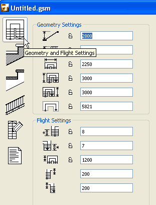
Stair/Slope Geometry and Flight Settings Tab Page
The parameters are separated in three or four sections, depending on the stair type chosen: Geometry Settings, Flight Settings, Winder Settings and Tread Settings. Depending on the parameters you set in these fields, the stair’s preview symbol (seen at top right in the dialog box) will change accordingly.
Many of the parameters you enter can be optionally locked by clicking the lock icon. If you do not lock these parameters, modifications on subsequent tab pages may cause StairMaker to automatically recalculate these values.
Locked parameters will not be modified and StairMaker will ensure that subsequent options you set are compatible with these parameters. If parameters need changing, StairMaker will skip locked parameters and look for the next value in the hierarchy.
If editing is not possible without changing a locked parameter or if too many parameters are locked, an alert will appear.
Enter numerical values to set the geometry of the stair. These parameters vary depending on the type of stair you are creating, and the icon will indicate which parameter is which.
These parameters may include:
•total height,
•flight width,
•full length, or lengths of lower and upper parts of the stair, or length of middle part,
•landing length,
•length of the walking line,
•for spiral stair with newel: initial and sweep angles.
Flight Settings
Enter values to set the parameters that define the flight. These parameters may include:
•number of risers,
•form and the number of the treads in the winder range (in the case of certain stair types),
•dimensions of the landings,
•value of the arrival offset,
•closing angle of the flights,
•surface material setting for newel post,
•lower and upper offsets of winders, for U-return stairs, and winder types (normal or radial),
•turning angle (for C-Run stairs),
•size of narrowest tread along the inside,
•offset of the walking line,
•winder type.
Winder Settings:
•Number of threads in winder
•Distance between the two flights (U stair)
•Offset(s) of risers in winders from the corner(s) of the stair
Tread Settings

Enter values in these fields to define the geometry of the Treads or (if you are editing a Slope) the angle of the Slope. To the right of these fields, the longitudinal section of the stair is shown, giving you instant feedback on your changes.
Set Riser Geometry: It is easier and more comfortable to climb the stairs if the sum of twice the riser and the run (2*Riser + Run parameter) is within the range of 60 to 63 cm, or 24 to 25 inches. To ensure this condition, you can define a range of values for the (2*Riser) + Run parameter in the Tread Settings section.
(2*Riser)+Run> Enter the minimum step value here.
(2*Riser)+Run< Enter the maximum step value here.
(2*Riser)+Run= The last parameter is not editable. It only shows the current value of the (2*Riser) +Run parameter.
Every time you modify a parameter, StairMaker checks that the (2*Riser) + Run parameter is still in the appropriate range.
Enter the run value here. To lock this parameter, click on the lock button.

Enter the riser value here. To lock this parameter, click on the lock button.

Locked parameters will not be modified. If parameters need changing, StairMaker will skip locked parameters and look for the next value in the hierarchy. If editing is not possible without changing a locked parameter or if too many parameters are locked, an alert will appear.
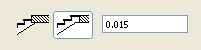
Optional top tread at floor level: Use the buttons at the bottom of the Flight Settings section to add an optional top tread to the stair. It may either have the same depth as the stair’s other treads, or you can customize an extra tread depth.
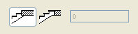
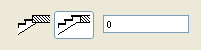
Click the button on the right to add a top tread to the floor level. A top tread is added to the stair at top floor level.
If you leave the extra tread depth field’s value at zero, the top tread at floor level will have the same depth as the other treads. To change the top tread’s depth, enter a positive value.
Check Stair: Click this button to detect any conflicts that would prevent StairMaker from generating the stair.
The Slope editing window is quite similar to the Stair editing window, but irrelevant symbols and parameter fields are dimmed and the others are transformed into slope setting functions.
In the Tread Settings section, a new element is the field where the angle of the slope can be set.
In the Structure tab page, the available structure types for the slopes correspond to the structure types for stairs.
For more information, see Geometry and Flight Settings (StairMaker).
Stair Structure & Landing Tab Page

Structure
The content of this tab page changes according to the construction type of the stair. These changes will also appear in the stair geometry tab page and in the parameters of the stair.
The following 3D alternatives are offered:
•Solid Stair with Treads
•Stair with Carriages
•Stair with Stringers
•Treads only
•Solid Stair
Enter the parameters relevant to the stair structure you have chosen:
Enter the stair slab thickness here:
If your stair has carriages, enter the carriage width thickness here:
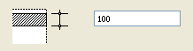
If you are making a stair with stringers, enter the side holder offset here.
The upper and lower slabs should be set to exactly join the Floor Plan Symbol within ArchiCAD, no matter which 3D alternative is selected in StairMaker, and even if a top tread at floor level is added to the stair.
Use the fields (pictured here) to enter values for the thicknesses of the stair’s upper connecting structure and its lower connecting structure. Each thickness has two components: subfloor and finish.
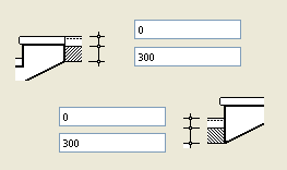
If you do not use any separate slab for subfloor + finish in your design, set the subfloor + finish thickness to zero.
StairMaker automatically adjusts the stair parameters to these slab specifications.
Landing
If your stair has one or more landings, enter values for one or both landing thicknesses in the Landing section of this tab page.
Clean Intersections: Click this button to open the Clean Up Bottom Surface dialog box. Use these options to create clean intersections at the bottom of the stair between the runs and landings.
Choose one of the first two radio buttons, depending on whether you want to adjust the landing thickness or the stair slab thickness:
•Adjust Landing Thickness to Stair Slab Thickness,
•Adjust Stair Slab Thickness to Landing Thickness.
Calculating Risers from Upper and Lower Landings
The other set of radio buttons will affect the stair’s geometry: it determines how the number of risers (as set in Geometry, Flights and Tread Settings tab page) will be counted: either from the bottom of the stairs upwards (Start Calculation from Downstairs) or from the upper landing downwards (Start Calculation from Upstairs).
StairMaker recalculates the parameters with the new values, and the 2D symbol of the stair will be updated.
Note: The “U Return with Two Landings” stair type has two landings; your settings will affect the lower landing and StairMaker will apply them automatically on the upper one.
Attributes
Define the pencolor used for the Stair’s contour and the Materials of each of the Stair’s sides in the 3D Window and PhotoRendering.
Check Stair: Click this button to detect any conflicts that would prevent StairMaker from generating the stair
For more information, see Structure and Landing (StairMaker).

Note: If you have chosen a Solid Stair or Solid Slope in the Stair Structure & Landing tab page, the Tread Parameters tab page is not available.
Enter values in the input fields of the Tread section of the tab page to define the exact parameters of the stair’s tread:
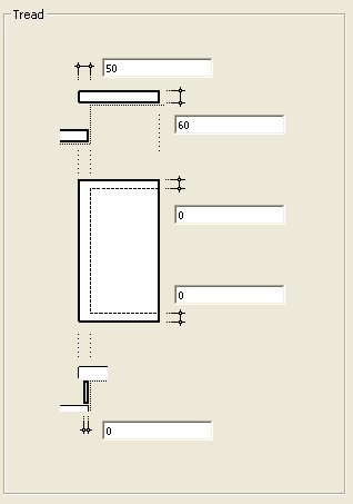
The input fields from top to bottom:
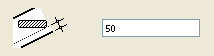
•define nosing on the front of the stair,
•define the thickness of the tread,
•define the thickness of the nosing at the right side and at the left side of the tread,
•define the thickness of the risers.
Attributes: Define a Pen Color for the tread’s 3D contours.
Use the materials pop-up palettes to define a separate material for each surface of the tread: the top, the front and the riser. To assign the same material to each surface, click the lock icon.
Check Stair: Click this button to detect any conflicts that would prevent StairMaker from generating the stair.
For more information, see Tread Settings (StairMaker).

Use the content of this tab page to set type, location and parameters for your stair railings. The settings displayed on the screen are always those relevant to the selected railing and any changes in the values of the parameters will only affect the selected railing.
Click one of the three Railing segmenting buttons at the top of the dialog box to set whether the railing settings should apply to. The mode chosen here is also in effect when setting the post.
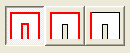
•All Stair-Rail Side mode: both sides of the entire stair. If you select this option, all segments in the stair preview will be selected, and your parameter settings will affect railings for the whole of the stair. A single railing type will be used for the whole stair with the same offset and parameter value for each segment.
When switching to this mode from either of the other two (One Side mode or One Segment mode) each flight inherits the stair-rail and post settings of the lower starting flight’s first left-hand segment.
•One Side mode: one side of the entire stair. If you select this option, the left and right stair-rails can be set independently. The left stair-rail is selected by default as displayed in the preview of the stairs. To switch to the right stair-rail, move the cursor to the other side of the stairs until it takes the form of a stair-rail, then click it.
When switching to this mode from All Stair-Rail mode, both sides inherit the settings chosen in the previous mode. When switching to this mode from One Segment mode, the whole flight inherits the settings of the lower starting segment.
•One Segment mode: a selected segment. Clicking the third icon allows you to define a railing for each flight (segment) independently. By default, the first segment of the left railing is selected. To select another segment, simply click it.
Different offset values can be used for each segment. In this case, the elements of the stair-rail belonging to different segments will not fit each other automatically. Positive or negative upper and lower overhang can be defined manually for each railing segment.
When switching to this mode from either of the other two (All Stair-Rail mode or One Side mode), all stair-rails inherit the previous settings. The overhang values of the stair-rails will be identical to those calculated automatically in the previous mode.
In the preview area that displays the floor plan of the stairs, each segment of the railing is represented by a line that shows where the centerline of the railing lies. To switch off a railing, first select it, then choose the No Railing option from the Railing type list. A thin line will indicate the place of the stair-rail.
Railing Setting: Choose types and parameters for the selected railing from this pop-up menu. The content of the list window depends on the available definitions. The railing preview area (above the stair-rail type list) shows a small image of the selected railing type.
Location
These controls define the direction of the railing’s offset with respect to the edge of the stair (inside the stair or outside the stair), as well as the value of the offset.
Parameters
Enter a value for the distance from the stair to the top of the railing (Top Height):
Enter a value for the distance from the stair to the bottom of the railing (Bottom Height):
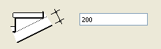
Enter a value for the railing’s overhang at the stair bottom (Lower Overhang):
Enter a value for the railing’s overhang at the top of the stair (Upper Overhang):
Note: In One Segment mode, the lower and upper overhang relates to the current segment, while in the other two modes they apply to the lower overhang of the bottom segment and the upper overhang of the top segment.
If you do not want the railing to go all the way from the bottom to the top of the stair, you can achieve this by using the Lower Overhang and/or Upper Overhang controls: If you set negative values to these options, then the railing will start/end with the overhang value that you defined.
Additional Parameters
These apply to the chosen railing type.
Post Setting
Use these controls to define the posts of the railing. If the selected type does not contain posts, this section will be dimmed.
Choose one of the four radio buttons to define the post placement.
•No Posts: Click this button to eliminate all posts from the railing.
•Closest to: Click this button to enter a value for the approximate distance between each neighboring post.
•On every Tread: Click this button to place posts on every tread (on landings, approximate distance will be used).
•Number: Click this button to set the number of posts.
Snap to Corner: Check this box to place a post at each of the segment ends, in addition to posts placed according to the rule defined by the chosen radio buttons.
Enter a value for offset of the posts above the railing.
Enter a value for offset of the posts below the stair.
Enter a value for the distance to offset of the first and the last posts from the ends of the railing.
Click this button to select the position of the posts relative to the centerline of the stair-rail.

Enter a value for the side offset of the post here.
Modify Post Location: After placing posts automatically according to your settings, you can modify the location of any single post by double clicking on the post on the selected stair-rail segment in the preview. A dialog box appears, where the position of the post can be set up numerically.
Check Stair: Click this button to detect any conflicts that would prevent StairMaker from generating the stair.
For more information, see Tread Settings (StairMaker).
Use this tab page to define the appearance of the Stair symbol in the project’s 2D windows.
For more information, see Symbol Settings (StairMaker).
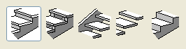
2D Detail Level
Click the black arrow to choose a Detail level preference for the Stair Symbol:
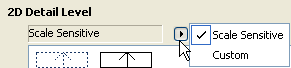
Scale Sensitive: Choose Scale Sensitive for the amount of detail shown in the 2D symbol to be scale-dependent.
Custom: Choose this if you want the Stair symbol to remain the same regardless of window scale.
The preview window in 2D Detail Level shows graphical symbols of many types. Choose the desired symbol type with which to display your Stair.
Walking Line Start Symbol
Choose the preferred symbol style to mark the start of your Walking Line (or None, for no symbol).
Walking Line End Symbol
Choose the preferred symbol style (arrowhead) to mark the end of your Walking Line (or None, for no symbol).
Rail Symbol Type
Choose the preferred symbol style to represent the Stair railing.
Check Stair: Click this button to detect any conflicts that would prevent StairMaker from generating the stair.
Attributes
2D Symbol: Choose a Line Pen and Line Type with which to display the 2D symbol of the Stair, for both the Visible and the Invisible Structure.
The Visible Structure is the part of the Stair below the Break Mark. The Invisible Structure is the part of the Stair above the Break Mark., as well as stair parts that are hidden by other parts of the structure.
Break Mark Type: Choose either Straight or Zig-Zag to display the Break Mark.
Background Fill Type: Choose a Background Fill for the body of the stair’s 2D symbol. Choose a Fill Pen and a Fill Background Pen for this Fill. Choose either On or Off to control the display of the Fill above the Break Mark.
Show Walking Line: Choose either On or Off to control the display of the Walking Line on the Stair’s 2D symbol. If you turn it on, choose a pen color and line type for the Walking Line.
Walking Line Start Symbol: Choose a Fill type for the Walking Line Start Symbol. (The Symbol itself is chosen on the left side of this tab page.)
Walking Line End Symbol: Choose a Fill type for the Walking Line End Symbol. (The Symbol itself is chosen on the left side of this tab page.) If the Walking Line is repeated within the Stair (if you have multiple End symbols), the “Fill Pen Above” control lets you set a separate Fill for the Walking Line End Symbols that fall above the Break Mark.
Text Display
Turn Readable Text option on if you want texts to be readable from the bottom and from the right, independent of the Stair’s position.
Turn Show Numbering on or off to control the display of numbering on all the treads in the stair.
Start From: Enter a number with which to start the numbering, as well as the Text Size and Text Pen.
Up and Down Text gives you the option of displaying the words “Up” or “Down” at the beginning of the walking line, or else no such text.
Turn Rise and Run Text on or off to control the display of Rise and Run information on the Stair Symbol. If you turn it on, the Stair will display the number of Rises and the number of Treads together with their dimensions.
Use the Format parameter to choose between different standards to display Rise and Run Text. Choose Custom Text to enter any text. Enter Text Size and Text Pen for the Rise and Run Text.
Description: Click this parameter to enable an empty text input field next to the parameter. Type any text you wish to appear on the Stair’s 2D Symbol. Set Text Size and Text Pen in the following two attributes.
Show Rail on Floor Plan: Choose either On or Off to control the display of the Stair’s Rail on the Floor Plan. (The Rail Symbol itself is chosen on the left side of this tab page.) If you choose On, set the following attributes:
•Line Type and Pen of the Rail
•Line Type and Pen of the Post (if the Railing has Posts)
•Show Rail Axis: Choose either On or Off to control the display of the Railing Axis on the Floor Plan. If you choose On, set the Line Type and Pen for the Rail Axis.
Show Carriage on Floor Plan: Choose either On or Off to control the display of the Stair’s Carriage on the Floor Plan. If you choose On, set a Line Type and Pen for the Carriage.
Story Sensitive: Choose either On or Off to determine whether the Stair Symbol should vary according to which story is visible.
Note: Stairs are shown on remote stories according to the options set in the Show on Stories control, in the Floor Plan and Section panel of this dialog box. If this control is set to “Home Story Only,” then the options affecting the stair’s Story Sensitive display are irrelevant.
If you set Story Sensitive to Off, then the stair appears on all stories in a uniform manner.
If you set Story Sensitive to On, set the following attributes:
•Line Type Below Home Story: Choose a Line Type for displaying the stairs on stories below the Home Story.
2D Above Home Story: Check the boxes to determine how to display the Stair on stories above its Home Story:
•Breakline: Set on or off to show or hide the Stair’s breakline on stories above the Home Story
•Show 2D Under Break Mark: Set on or off
•Show 2D Above Break Mark: Set on or off
•Show Treads: Set on or off to show or hide Treads on the Stair Symbol on stories above the Home Story.
•Line Type: Set the Line Type for the Stair symbol on stories above the Home Story
•Line Pen: Set the Line Pen for the Stair symbol on stories above the Home Story
•Walking Line Type: Set the Walking Line Type for the Stair symbol on stories above the Home Story
Stair Listing Settings Tab Page

Each element and property of the stair can be listed with the Document > Schedules and Lists menu commands. Stairs will be listed as library parts. The list can be set up individually in ArchiCAD; however, if you wish to list a part of the stair, be sure that the box beside it (in this tab page) is checked.
For more information, see Calculation.
Stair Tags and Categories Panel