Interior Elevation (IE) Tool Settings
For a description of generic settings common to all tools in the Toolbox, see Working in Tool Settings Dialog Boxes.
For details, see Interior Elevations (IE).
Interior Elevation General Panel
Settings in this panel depend on whether the selected Interior Elevation (IE) is the whole IE Group, or one of its viewpoints. If nothing is selected, the default settings are those of an IE Group.
For an IE Group:
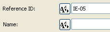
Reference ID: Enter any customized ID, if desired, or click the Autotext button to choose an Autotext reference as part of the ID.
Name: Enter any customized Name, if desired, or click the Autotext button to choose an Autotext reference as part of the Name.
For an individual IE viewpoint:
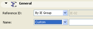
Reference ID/Name: To inherit the ID or Name defined in the parent IE Group’s settings, leave the pop-up on “By IE Group.”
Any Autotext defined in the parent IE Group’s ID/Name settings will be interpreted individually for each viewpoint in the group.
To enter any other ID/Name for this viewpoint, switch the pop-up to Custom and enter the desired text.
Marker Reference to: Choose an item whose information you want to display in the IE marker:
•the Interior Elevation viewpoint, identifying it by its location in the Navigator Project Map;
or
•the first placed drawing of the Interior Elevation viewpoint, identifying it by its location in the Layout Book hierarchy
Reference to: shows the path (location in the Navigator hierarchy) of the chosen reference item.
To redefine the Marker Reference: Choose from among the pop-up choices (either viewpoint or first placed drawing of the viewpoint).
Interior Elevation Status
Choose an option to define the status of the link between the Elevation and the Floor Plan.
•Auto-rebuild Model: An Interior Elevation with Auto-rebuild status will be automatically rebuilt every time it is opened or brought to the front of the screen if the Floor Plan has changed.
•Manual-rebuild Model: An Interior Elevation with Manual-rebuild status is not rebuilt automatically. It can be rebuilt from the model only by using the Rebuild Elevations/Rebuild from Model command of the View menu.
•Drawing: In an Interior Elevation of Drawing status, elements will be exploded into 2D drawing elements which are not linked to the Floor Plan and will not be automatically rebuilt from the model. You can, however, update the drawing to reflect recent changes made to the model.
This pop-up list allows you to choose the stories on which to display the Interior Elevation markers and lines.
•If you have selected the Infinite radio button under Vertical Range, choose All stories or a particular custom story (choose the story shown in the pop-up list, or choose Browse Story to select another story of the project.)
•If you have selected the Limited radio button under Vertical Range and entered height values, two additional options are active.
Entirely in Range: The Elevation marker and line will appear on all stories that are entirely in the vertical range defined in the height value fields.
At Least Partly in Range: The Elevation marker and line will appear on all stories that are at least partly included in the vertical range defined in the height value fields.
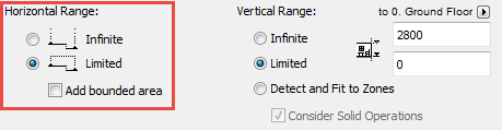
The Horizontal Range can be either Infinite or Limited.
The default choice is Limited. In this case, the IE view will extend horizontally until the Room Boundary line.
If the Room Boundary is a Wall, then the view automatically extends to the depth of the Wall.
To adjust the horizontal range, select the Room Boundary line and stretch or shrink it using the commands of the pet palette. (Stretch/shrink modifications to this segment will affect the neighboring line segments accordingly, as when editing any polyline.)
An Infinite Horizontal Range means that the Interior Elevation viewpoint will extend horizontally to include all visible parts of the model.
Note: The visibility of elements in an Interior Elevation is defined differently as of ArchiCAD 18. In earlier versions, the bounding box of elements determined whether they would be shown in the viewpoint. To use the older-version logic, turn on the Interior Elevation Legacy checkbox in Project Preferences. (See Legacy Preferences.)
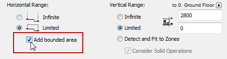
Add Bounded Areas (Interior Elevation Default Settings)
To include connected enclosed areas in the Interior Elevation viewpoint, choose Add bounded areas. This checkbox is available
•in Interior Elevation Default Settings (you must set it before you place the IE; you cannot set this control for an already placed IE)
•if the Limited option is checked for Horizontal Range
Vertical Range
The vertical range defines the height of the Floor Plan Elevation that will be included in the Interior Elevation window.
•Infinite: The Elevation will include the entire height of the project.
•Limited: The Elevation is confined to a limited vertical range. If you click this button, enter elevation values for the upper and lower limits of the Interior Elevation. Elements above and below these limits will not appear in the Interior Elevation.
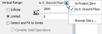
Use the pop-up to define whether this vertical range should be measured from Project Zero, or a particular custom story: choose the story shown in the pop-up list, or choose Browse Story to select another story of the project.
•Detect and Fit to Zones: The Interior Elevation will use the Zone height (if it detects any zones in the Interior Elevation limit) as the IE viewpoint’s vertical range.
If you want this zone calculation to take any Solid Operations into account, you should also check the Consider Solid Operations box.
Interior Elevation Marker Panel
Marker Placement: Use this control if you are creating a Group of IE viewpoints. Choose one of these options:
•Individually for Each Viewpoint: You will place as many markers as viewpoints you are creating in the Group.
•One common Marker for the IE Group: You will place a single marker for the entire group of viewpoints.
Select Marker Type pop-up: Select a parametric marker from this list.
The chosen marker’s 2D Symbol appears in the preview window.
Marker format: Choose a pencolor, penweight, font, text size, height, and text style to format the marker.
Use Symbol Colors: Check this box to ignore Pencolor setting above and use Pencolor used when the element’s 2D symbol was created.
The parameters of the corresponding GDL Object appear in the parameter list fields. Use the parameter fields to define custom text for Drawing ID and Layout Number, if you wish.
Note: Many parameters in this list can also be set using a graphical interface in the Marker Head panel; the settings are identical.
Interior Elevation Marker Head Panel
Choose from the available Marker Heads for the parametric, GDL Object type markers. These options vary depending on the Markers loaded in your library.
Note: In Interior Elevation Selection Settings, this panel is only available if the Marker Placement option (in the Marker panel of this Settings dialog box) was set to “Individually for each Viewpoint” when the Interior Elevation viewpoint was created. Otherwise, this panel is grey.
Fill type: If you choose a Marker Head that includes a fill, this control is active. Choose the desired fill type for the Marker Head.
Pen: Choose a pen for the Marker Text.
First Text Row: Use these controls to define the Marker’s first row of text (or Inner Text, if you have chosen a single IE marker). The options available depend on the type of marker reference you defined in the General Panel.
For example, if you chose “Marker Reference to: first placed drawing”, then the First Text Row will show “Referred Drawing”, and the Drawing ID checkbox below is active.
Refer to the preview window of the Marker Panel to see how your choices affect the Marker.
Second Text Row: Use these controls to define the Marker’s second row of text (or Outer Text, if you have chosen a single IE marker). The options available depend on the type of marker reference you defined in the General Panel.
Interior Elevation Model Display Panel
Use these controls to define how to display the contents of the Elevation Viewpoint.
CUT ELEMENTS
“Cut” elements are those cut by the Elevation plane.
Fill Cut Surfaces with: This control gives you four options for displaying the surfaces of cut elements in the Elevation:
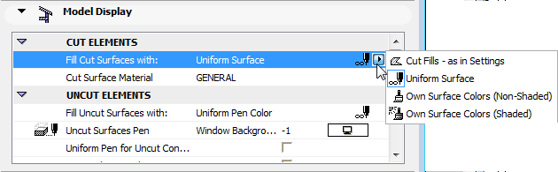
1.Cut Fills - as in Settings: Cut surfaces will use the Building Materials assigned to the individual elements.
In this case, an additional option is available:
Uniform Pen for Cut Elements: Check this box to use the same pens to display all the cut elements in this Elevation. (If you don’t check this box, the cut elements will use the pen settings of the individual elements).
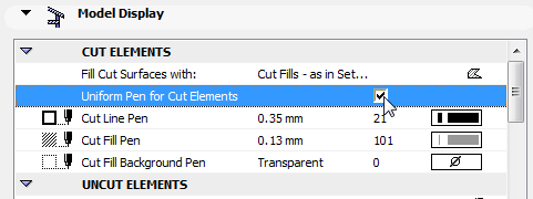
Then define the pen using the following controls:
•Cut Line Pen
•Cut Fill Pen
2.Uniform Surface: This option means that all cut surfaces in this Elevation will use a single surface.
•Choose this uniform surface using the fill pop-up of the Cut Surface parameter
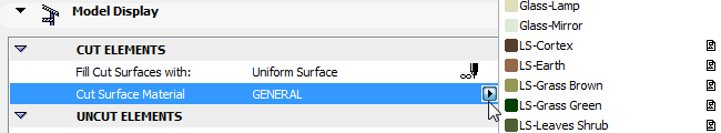
or
•Check the box Use Surface Defined for Cut Elements in 3D. This is the surface you choose in View > Elements in 3D View > Filter and Cut Elements in 3D.
See Filter and Cut Elements in 3D Dialog Box.
See 3D Cutting Planes for information on 3D Cutting Planes.
3.Own Surface Colors (Non-Shaded): This option means that all cut surfaces in this Elevation will be shown using the surface assigned to the individual elements through their building material.
4.Own Surface Colors (Shaded): Choose this option to display uncut fills in this Elevation using the elements’ own surface colors. The display colors will reflect shading effects.
Uniform Pen for Cut Elements: Check this box to use a single set of pens for all the cut elements in this section. (If you don’t check this box, cut elements in section will use the pen settings of the individual elements). Then define the pen using the following controls:
•Cut Line Pen
•Cut Fill Pen
These settings apply to all the cut elements in this Elevation.
Hide Cut Elements: Check this box if you do not want elements that are cut by the Interior Elevation Line to be displayed in your Interior Elevation viewpoint. If you check this box, the “Cut Fill and “Cut Line” options below will not be available.
UNCUT ELEMENTS
Choose pen attributes for uncut elements displayed in this IE.
Fill Uncut Surfaces with: Use this control to define the fill of uncut surfaces displayed in this Elevation. Applying a fill means that you will be able to quick-select these surfaces in the IE.
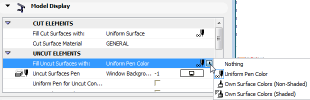
•Uniform Pencolor: Choose a pencolor to apply to the fills of all uncut surfaces in this IE.
To display Surface colors in Interior Elevation view (on uncut parts of the IE only), choose one of the two following options:
•Elements’ Own Surface Colors (Shaded): Choose this option to display uncut fills in this IE using the elements’ own surface colors. The display colors will reflect shading effects.
•Elements’ Own Surface Colors (Non-Shaded): Choose this option to display uncut fills in this IE using the elements’ own surface colors. The display colors will not reflect any shading effects; each surface color will be uniform over the whole surface.
•Nothing (no color applied to uncut surfaces)
Note: Using the Fill Uncut Surface option may increase rebuild time for large models. If this is a problem, choose “Nothing”.
Uniform Pen for Uncut Elements: Check this box to use a single pencolor for all uncut elements in this IE. The color chooser control below is then activated; choose the desired color. This color will also be used for fill contours.
If you leave the box unchecked, then uncut elements will be displayed with their original pens.
Vectorial 3D Hatching: Check this box to activate vectorial 3D hatch patterns in this Interior Elevation.
Transparency: Check this box to give see-through Surfaces (e.g. glass) a transparent effect in this Interior Elevation.
Exclude View Blocking Walls: Check this box if you do not want intervening walls to be displayed in your Interior Elevation viewpoint.
SUN AND SHADOWS
Viewpoint Sun Settings: Choose one of two sun positions relative to the Elevation Line:
•As in 3D Window: Use this option to inherit the sun position set up in the 3D Projection or 3D Perspective Settings dialog box.
See also 3D Window.
•Custom: Use the Sun Azimuth/Sun Altitude controls below to define a custom sun position for this Elevation by typing the desired value into the corresponding field. Azimuth values are limited so that the sun is always behind the Elevation line. Otherwise the visible side of the building would be overshadowed.
Note: The sun position can be activated individually for every Elevation window.
Sun Shadows: Check this box to activate the controls related to Sun Shadows. Shadows work independently of vectorial 3D Hatching patterns.
Shadow Polygons: In Interior Elevations, shadows have no contours; however, the fill polygons are freely customizable. Choose the fill type, Fill pen and Fill background pen using the corresponding pop-up palettes.
Note: You cannot choose a custom fill as a shadow if your uncut surface fills are set to use “Own Surface Colors.”
Interior Elevation Story Levels Panel
Use the controls in this panel to define the display of Story Level lines and Story Handle Markers on this Elevation.
Show Story Levels: This pop-up list allows you to choose how to display story lines on this Elevation.
•Display only: Story lines will appear only on-screen, but will not be displayed in the output.
•Display and Output: Story lines will appear both on screen and on the printed output.
•None: Story lines will not be displayed on this Elevation.
For information on Story Level Lines, see Story Level Lines.
Choose a line type and pencolor for the story level lines.
Markers & Story Level Lines: The left and right check boxes determine whether to display the left and right Story Markers.
The center checkbox determines whether to display the Story Level Line itself.
Note: You cannot uncheck this box if the Offset values of the Story Handle Markers are both set to zero.
Use the Design > Edit Story Levels command to adjust story levels in this window.
Offset to IE Boundary: Enter a value for the offset of the Story Level line beyond the limits of the IE (defined by the Interior Elevation Line drawn on the Floor Plan).
Story Marker pop-up: Choose the default Marker or another loaded Marker object.
Choose a font type, encoding, font size and marker size for the components (text and symbol) of the chosen Story Marker.
Story Markers are parametric GDL Objects. Their parameters can be adjusted in the parameter window in this panel. If the object definition contains a script, the Story Handle Custom Settings panel is activated.
Interior Elevation Story Handle Marker Custom Settings Panel
This panel is active if the Story Level Marker type (selected in the Story Levels Panel) contains a relevant GDL script.
Interior Elevation Grid Tool Panel