Ambient Occlusion (CineRender Effect)
This effect is available in the Detailed view of PhotoRendering Settings for the CineRender engine.
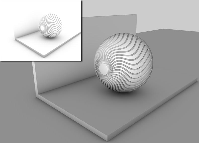
Ambient Occlusion (AO) determines the degree to which each visible surface point is exposed and darkens it accordingly. Ambient Occlusion (AO) offers, within certain limits, a fast alternative to GI.
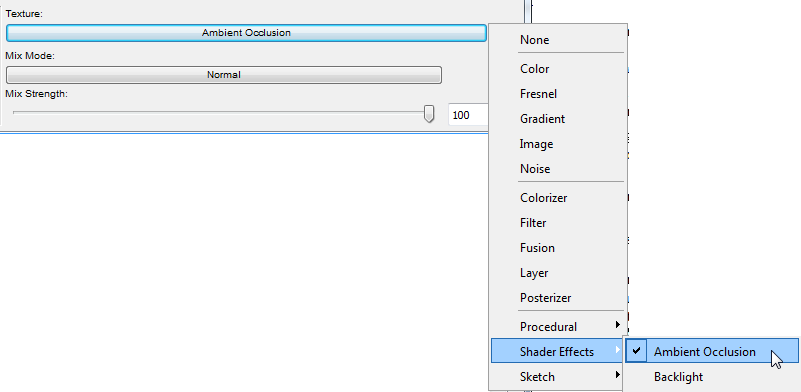
Note: As an alternative to using AO as a global effect on the whole Rendered scene, Ambient Occlusion can be applied as a shader effect to specific Surface Channels.
See Ambient Occlusion (CineRender Surface Channel).
Let’s say your scene is surrounded on all sides by a sky. The AO shader will determine to what extent each visible area sees the sky.

Corner areas, holes, and areas between objects placed very close to each other will see less of the sky and will therefore be darkened in accordance with the AO settings.
As of ARCHICAD 20, two types of Ambient Occlusion calculation are available:
•the usual "brute force" method, which checks the environment’s visibility for each individual pixel
•the faster method via Cache, which only checks certain points’ visibility and interpolates all others in-between.
The latter works internally, similar to the Irradiance Cache GI mode, and is controlled using similar settings. The advantage of using this method is that the AO calculation is much faster.
See Cache, below.
Color
Use the Color option to define the color gradient that AO assigns, dependent on exposure. Normally, it will be a simple custom black to white gradient but other colors can also be defined.
Be aware of the fact that these gradients will be treated as grayscale, depending on the material channel.
See also Adjusting Gradient Parameters.
General
•Minimum Ray Length: Determines how the gradient defined in Color will be rendered between exposed and non-exposed areas. The closer the Minimum Ray Length value is to the Maximum Ray Length value, the further the gradient will be pushed towards the edges, which are defined by the maximum ray length.
This value shouldn’t really be tampered with. Leave it set to its default setting of 0.
•Maximum Ray Length: This value defines to which distance the surfaces see each other. Where geometry meets, as with the floor and wall or the sphere and floor, even small rays will fall upon surfaces, which is enough to darken those areas.
If high values are used, a much larger distance will be included within which objects will be able to see each other. This results in a softer, more homogeneous darkening that will cause longer render times.In general, lower values are recommended.
•Dispersion: During each AO calculation, several rays (Samples) will be emitted for each point within a virtual hemisphere in the scene. These samples check to see if any geometry lies within the Maximum Ray Length. Dispersion determines to what extent these samples will be taken into account on the hemisphere’s surface. A value of 0% takes only the hemisphere’s zenith (vertically over the sphere) into account. A value of 100% will take the entire hemisphere into account.
Accuracy, Minimum Samples and Maximum Samples (Ambient Occlusion)
These settings are responsible for AO quality.
•Low quality is accompanied by grainy results. This is not necessarily bad. In fact, in some cases, this can be of high aesthetic value.
•If you prefer homogeneous, seamless transitions, you should select higher quality settings, which will also increase render times.
In simple terms: Samples are required to render AO. The more samples that are used, the more homogeneous (less grainy) the rendering will be - the longer the render times will be as well. Fewer samples, on the other hand, result in shorter render times.
Of course a maximum number of samples can be calculated for the entire scene. This would take very, very long to calculate and it does not make any sense since a scene contains many areas in which a relatively small number of samples would suffice.
That’s what the Minimum Samples and Maximum Samples settings are for. They are used to affect the critical and less critical areas of your scene in different ways.
The Accuracy setting determines where and in what amount samples must be distributed in order to achieve the best possible result. In critical areas, the maximum amount of samples will be used.
Hence, the Accuracy setting has the most influence in critical areas (since higher values in these areas lead to more samples) and less influence in less critical areas, which use the Minimum Samples value.
•Contrast: Use this setting to adjust the AO effect’s contrast. Negative values can also be entered!
•Use Sky Environment: AO can work without a separate light source if the Physical or HDRI Sky is used as Illumination. If the Environment’s Sky checkbox is active, the reflected sky color will be multiplied onto the final AO image.
Note: For this to have an effect, the Ambient Occlusion texture must activated in the Environment or Luminance surface channels.
See Ambient Occlusion (CineRender Surface Channel).

•Evaluate Transparency: When this option is active, transparency will be analyzed on the basis of the Transparency or Alpha surface channels. In doing so, the degree of transparency will be taken into consideration: A semi-transparent sphere will still cause some AO in spite of this option being active.
•Self Shadowing Only: When this option is active, separate objects will not see each other, they will only see themselves.
Because AO works similar to Irradiance Cache, the settings are for the most part the same. In most cases, you will only have to adjust the Record Density setting.
Record Density
Record Density defines the subordinate parameters automatically. You should modify the subordinate parameters separately only if the AO is consistently wrong or if it does not appear to be precise enough.
Enable Cache
•If enabled, the AO cache (described briefly in the section below) will be used.
•If disabled, AO will work as in previous versions of CineRender (pre-AC20): The environment’s visibility will be calculated for each pixel.
How the AO Cache Works
During rendering, several pre-calculations take place (pre-passes), during which the project is analyzed for the regions most important for the camera (“shading points” in corners, concave regions, etc.) for visibility of the environment and to calculate an AO value:
All AO values will be cached to an AO cache and can be saved as a file for later use.
In a second step, the selectively located AO values will be interpolated and smoothed.
The following settings primarily serve to disperse the shading points.
Samples
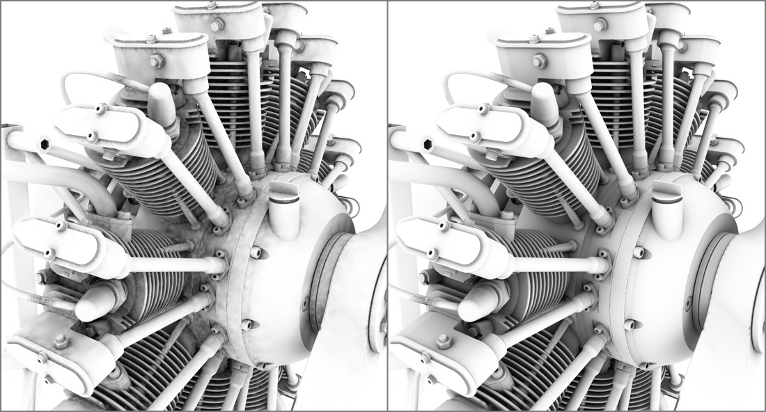
This is the number of samples that are emitted hemispherically from each shading point. If the AO looks spotty, this is the value that should be increased.

Left: small Samples value. Right: larger Samples value. Model by Steen Winther.
Min Rate/Max Rate
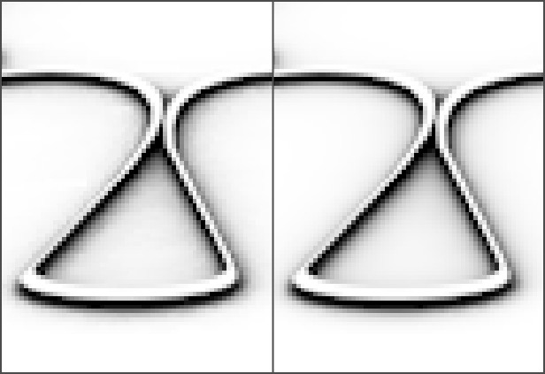
These two settings can, for the most part, be ignored. The effect they have is barely visible. The “worst” setting for Min. Rate and Max. Rate (-8 for each) differs only slightly from their “best” settings (-8 and +4, respectively (see image).

8/-8 (left) and -8/+4 (right) for Min. Rate and Max. Rate, respectively
Nevertheless, their function should be mentioned: While the pre-passes are being rendered (the phase in which the squares are at first large and become increasingly smaller) the dispersion of the render density is defined. This is an adaptive process that places particular emphasis on the critical regions. The difference between the Min. Rate and the Max. Rate defines the number of pre-passes.

-7 and 0 for Min. Rate and Max. Rate, respectively
A value of 0 will result in full image resolution (pixel size 1*1) and a value of -1 will produce a pixel size of 2*2, -2 = 4*4 and so on. The Min. Rate value should therefore be less than or equal to the Max. Rate value. Positive values can also be used, which will allow caching in the sub-pixel regions (for example, this could be useful, in conjunction with Subpolygon Displacement, if details get lost).
Density/Minimum Spacing/Maximum Spacing
These three settings work together to define the general shading point density at critical and non-critical areas:
•Density: The general shading point density in consideration of the following to settings.
•Minimum Spacing: The shading point density at critical areas (e.g., corners).
•Maximum Spacing: The shading point density at non-critical areas (e.g., planar surfaces without elements that block the view). Various values for this setting can be seen if you take a look at the GI’s Density setting. The shading point dispersion is exactly that of the AO cache dispersion.
Smoothing
All of the settings just described revolve around the placement of shading points and their calculation.
AO was ascertained selectively at numerous locations within the project. The selective dispersion must be turned into a flat dispersion for rendering. A smoothing algorithm does this as follows: For each pixel to be rendered on an object’s surface, the AO cache is checked for those instances nearest to that pixel and their values will be interpolated for that pixel.
In brief: Values that are too low will result in spotty AO; higher values will result in more homogeneous renderings (but even these ignore Samples that are too low). Generally speaking, higher values take into consideration more shading points for the rendered pixel.
Paradoxically, extremely large values will also lead to spotty results.
Screen Scale
If disabled, the output size for rendering is irrelevant for ascertaining the shading point density. It will remain constant, regardless if you render at a resolution of 80*80 or 3000*3000. For the former it would be too large and for the latter, too small.
If enabled, the shading point density will be linked to the output size for rendering. This will result in a more flexible and adaptive shading point density.