Shader Effects (CineRender Surfaces)
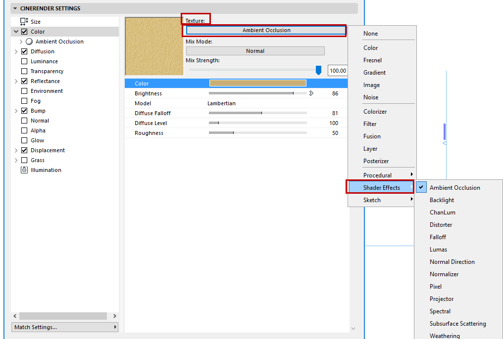
This group of shaders is found in the Shader Effects sub-menu of the Surface channel’s Texture pop-up:

These shaders are listed below with a brief explanation of their parameters.
Ambient Occlusion (CineRender Surface Channel)
ChanLum, Subsurface Scattering, Backlight
Ambient Occlusion (CineRender Surface Channel)
Ambient Occlusion for CineRender can be found in two locations in the interface:
•In Surface Settings, as a channel shader (see screenshot above).
•In PhotoRender Settings (Detailed view), as a global effect and calculated throughout the entire scene in Render Settings.
See Ambient Occlusion (CineRender Effect).
AO options in both locations are identical.
ChanLum, Subsurface Scattering, Backlight
These shaders all have to do with collecting light. Some surfaces have the ability to direct light inward, where it is dispersed (e.g. a wax candle or frosted glass).
Normally, light can only shine directly onto the surface of an object and cannot, for example, be transmitted further from the illuminated back side of an object to its front that lies in a shadowed region. Several shaders are available to help remedy this in their own way.
These shaders should be loaded into the Luminance channel. In this channel, the brightness these effects generate can be used as an illumination effect or added to the surface’s brightness.
ChanLum
From a defined distance from the object surface outward, the ChanLum shader observes the environment surrounding the object and samples light rays. This light is then used to brighten the surface of the object. This may not be realistic according to the world of physics but is often sufficiently accurate to simulate light that does not penetrate too deeply into a given surface.
Subsurface Scattering
This shader causes light to penetrate a surface where the light is dispersed. If the distance traveled by the light within the object is less than the defined value, the light can emerge again at a different location. This shader is well-suited for use on backlit objects.
Here, a candle that is simply illuminated by a light from above, which is used to simulate the flame. This light source is only able to illuminate the surfaces at the top end of the candle.
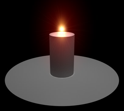
Here is the same scene with a ChanLum shader added in the wax surface’s Luminance channel. You can see how the light now continues around the top edge of the candle to also affect the sides. It also looks as if the candlelight were seeping through the edge a little.
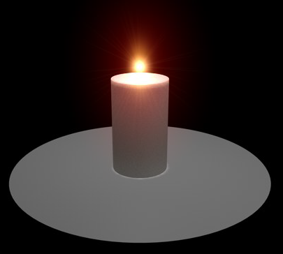
Here, a Subsurface Scattering shader was also added to the Luminance channel. The light now affects a large part of the top half of the candle but does not accentuate the edge very well. This type of lighting scenario is less suited for Subsurface Scattering because of the small angle that lies between the angle of view and the rays of light.
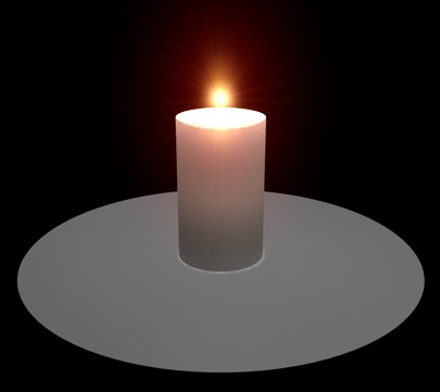
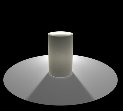
Here, the angle of view is increased by placing the light source behind the candle: now the Subsurface Scattering shader is well-suited: the light actually shines through the candle and the top edge is affected, as we wanted, thanks to the more intense light.
Backlight
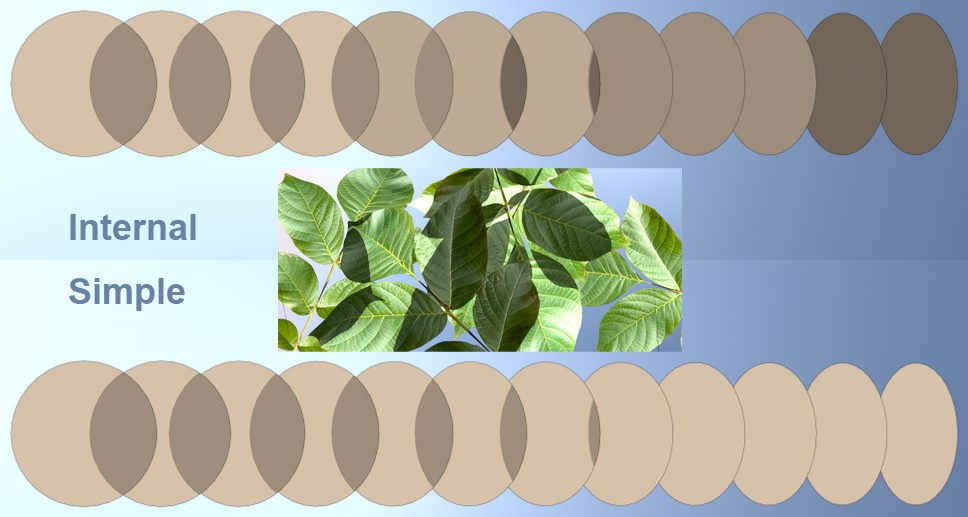
Allows you to gather illumination from the back face of an object. This gives the ability to create translucency effects with backlighting, such as rice paper or a thin leaf lit from the opposite side complete with shadowing.
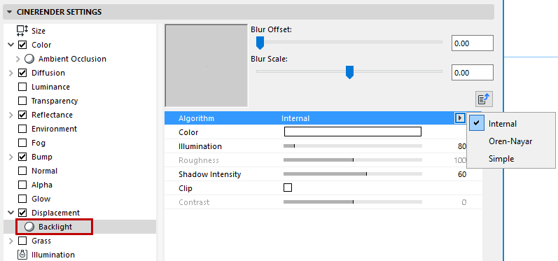
Algorithm: Use this setting to define the shading algorithm for the backlighting.
•Internal is equivalent to the common Phong shading.
•For Oren Nayar, see Model.
•Simple generates no shading at all, so that backlit objects are rendered uniformly bright. This is particularly well suited for very thin surfaces such as leaves, blades of grass, etc.
Distorter takes the value of an input channel and distorts it using the value from another texture channel.
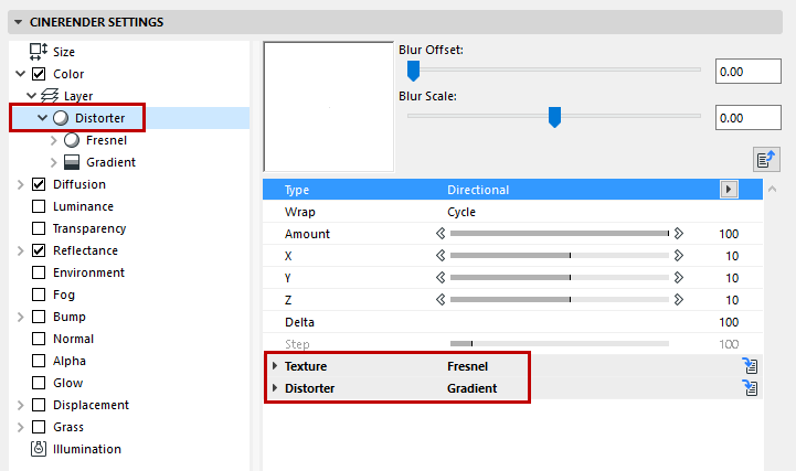
Type: The distortion algorithm to be used.
•Directional: The value of the distortion channel is added to the sample coordinate of the texture.
•Bidirectional: The value of the distortion channel is added to the sample coordinate of the texture if the value is between 50-100% and is subtracted if the value is between 0-50%.
•Flow Field: The distortion value is determined by evaluating the flow direction of the distortion texture and then the flow direction vector is used to offset the sample coordinate of the texture.
Wrap: The Wrap function controls what happens to parts of the texture that have been distorted and now lie outside the UV map. These can be ignored (None), repeated (Cycle), cut off (Clamp) or mirrored (Seamless).
Amount: Global distortion amount. 100% means distortion values from 0 to 1 in UV and 0 to 10 in 3D.
X/Y/Z: X is the distortion amount in U for 2D and X for 3D. Y is the distortion amount in V for 2D and Y for 3D. Z is the distortion amount in Z for 3D.
Delta: Delta is a scaling factor to use in sampling the texture for evaluating slope to be used in the bump channel. This allows you to get very sharp bump with minute detail that is not possible with the standard bump delta.
Step: Relative step size to be used in evaluating the flow direction in Flow Field distortion type.
Texture: This is the source image or shader to distort with the Distorter texture. You can bring in and affect any image or channel shader available to CineRender.
Distorter: The distorter texture is used to distort the texture defined by Texture (see above). The value of the distorter image or shader is used in the distortion algorithm to offset the sampling of the texture.
Falloff calculates the falloff between a custom vector and the surface normal. When the vector is the same as the surface normal, the value is 1, and when it points completely away, the value is 0. Falloff then remaps the value using a gradient.
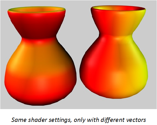
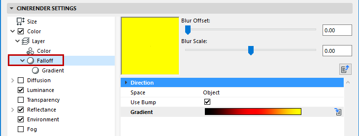
Direction [XYZ]: The vector to falloff from in 3D space.
Space: The space to calculate the falloff in.
•Object: The vector is specified in object coordinates and the falloff is affected by the object’s orientation (and by the orientation of the texture axis). In this way, the falloff sticks to the object as it changes rotations.
•World: The vector is specified in world coordinates and is not affected by the object’s orientation. This is the most common setting because it allows the object to move and have the falloff stay oriented in a consistent direction.
•Camera: The vector is specified in coordinates relative to the orientation of the camera. In this way, up is always up (in the camera view, for example) regardless of camera or object orientation.
Use Bump: If enabled, the bump normal is used to calculate the falloff. If off then the bump normal is ignored.
Gradient: The gradient used by Falloff to remap the value.
Lumas is an illumination shader that includes three specular highlights and the ability to simulate the anisotropic scratches that tend to produce elongated highlights in particular.
An anistropic effect is the mirroring of a surface, caused by small, inconspicuous scratches. You have probably seen this effect often on metal surfaces that are somewhat older in the form of concentric scratches on the surface
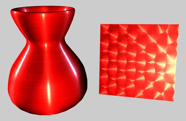
Lumas is useful in combination with Fusion and other channel shaders or images.
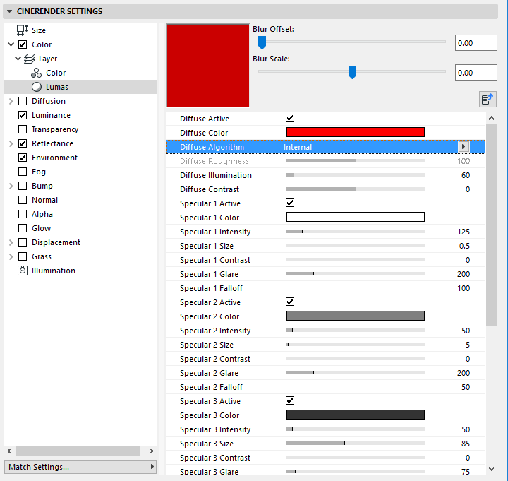
•Diffuse Active
•Diffuse Color: Sets the base diffuse color of the surface.
•Diffuse Algorithm: Specifies which illumination model Lumas will use.
•Internal is the standard Lambertian model
•Oren Nayar, which provides for a roughness variable allowing the user to go from simple surfaces (0 Roughness, identical to Lambertian), to complex rough surface (1+ Roughness, which provides a matte surface, such as linen or dirt).
•Diffuse Roughness: Dictates how rough the Oren Nayar illumination model will be. Zero is no roughness while 100% or greater is very rough. Experimentation is required to fully understand this parameter. This option is only available if Oren Nayar is selected in the Algorithm drop-down list.
•Illumination: Scales the Color to produce attenuation in the illumination of the surface (this simply means it makes the color darker when the value is close to zero and brighter when the value is closer to 100% or above).
If you are using the Oren Nayar illumination algorithm, you may want to bump up the illumination by about 10% to 20% because it renders darker usually. Appropriate values are between 0% to 200%.
•Contrast: Provides contrast for the result of the Color. Zero causes no effect, 0% - 100% causes standard contrast, above 100% causes a wrap contrast (the values that go above 100% wrap around to 0% again), negative values provide an inverse contrast to simulates surface that seem luminescent, such as silver. Appropriate values are -500% to 500%.
Specular Highlight Settings (Lumas Shader)
The specular highlights controlled in the Reflectance channel are added to the surface color. All three specular highlights share the same parameter set, which is described below.
•Active: Use this checkbox to individually activate or deactivate each specular light.
•Color: Sets the base specular color for the specular component.
•Intensity: Scales the Color to produce attenuation in the specular reflection of the surface (this simply means it makes the color darker when the value is close to 0% and brighter when the value is closer to 100% or above). The appropriate range is 0% - 1,000%.
•Size: Sets the size of the specular reflection. Appropriate value range for Size is 0.001% - 200%.
•Contrast: Provides contrast for the result of the specular sample color. Implements a standard contrast function. Appropriate values are 0% - 100%.
•Glare: Works with Intensity by using the edge falloff (multiplied by the Falloff scalar) to change the intensity of the specular reflection. This can be used to add a glare to the surface when a light is reflecting more on an edge or specular effects to reduce the specular reflection when a light causes a reflection closer to the edge. Appropriate values run between 0% - 200%.
•Falloff: Utilized to vary the falloff of the center of the object to the edge to affect the Glare intensity. Smaller values cause the specular reflection to reflect the Intensity value more, while larger values make the surface use the Glare scalar more. Experimentation is required to fully understand this parameter.
Anisotropy: Anisotropy is the property of being directionally dependent (as opposed to isotropy, which implies identical properties in all directions.)
Projection: The type of projection is used to define the anamorphic (disproportional) scaling of the specular highlights. It can also define the scratch direction to be used with the reflection and environment convolution groups.
•Planar: A flat XY planar projection.
•Auto Planar: Automatically projects on a plane parallel to the current normal.
•Shrink Wrap: A spherical projection for scaling direction, but uses a separate algorithm for projecting the scratches.
•Radial Auto Planar: Automatically projects on a plane parallel to the current normal.
•Radial Pattern Auto Planar: Creates a multi-origin radial scratch pattern that is parallel to the current normal.
•Radial Planar: Creates a radial scratch pattern originating at the center of a plane parallel to the current normal.
•Radial Pattern Planar: Creates a multi-origin radial scratch pattern that is parallel to the current normal.
Projection Scale: Scales the scratch algorithms that have an actual pattern (Radial Pattern is the only current algorithm of this type to which scale applies).
X Roughness/Y Roughness: Scale the highlights in the X and Y directions defined by the Scratch Projection algorithm. The appropriate range is 0.1% to 10,000%. If the X & Y roughness are the same, the standard internal specular algorithm is used.
Specular 1/Specular 2/ Specular 3: These check boxes specify which specular channels will be affected by the anisotropic scratches.
Amplitude: Scales the effect of the scratch of the specular highlights. The higher the value, the more scratched the speculars will look. The appropriate range is 0% - 100%.
Scale: Scales the scratch pattern itself. This applies to all scratch algorithms.
Length: Defines the scratch length in the space of the scratch pattern. Smoother milled surfaces would use a higher scratch length and rougher surfaces would use smaller values. The appropriate range is 1% - 1,000%.
Attenuation: Scales the amount of detail of the scratches based upon the samples, angle to the camera and the distance from the camera. The larger the values, the greater the attenuation, causing less scratching (better for animation); the smaller the value, the greater the detail (better for still images). The appropriate range is 0% - 1000%.
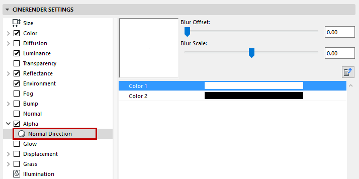
This shader colors an object based on the direction of its surface normals. Surfaces whose normals point towards the rendering ray take Color 1, the other surfaces take Color 2.
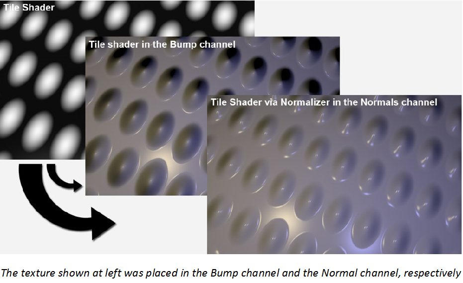
Using the Normalizer shader (placed into the Normal channel) you can use common textures that were usually used in Bump maps in the Normal channel. The Normalizer evaluates the contrasts to ascertain the location of edges and uses this information to calculate a Normal map.
As a reminder: Normal and Bump maps basically work the same. Information coded in RGB images affect an object’s (geometry) surface Normals when rendered and feign a detailed structure. Contrary to Bump maps, Normal maps can also “alter” the direction of the Normals, which makes it possible to create realistic effects (note the specular light on the bumps in the image below).
The Pixel Shader creates a pixel-like distribution of a texture.
Let’s say you want to project a texture made up of small areas of the same color onto a surface (e.g. a TFT display). You would want the individual pixels to also look good close up. This is where the Pixel Shader works its magic - it creates a fitting “pixel coarseness” without having to make changes to the original texture.
![]()
Note: The Pixel Shader only works with 2D Shaders and textures. When using a Noise Shader, for example, the Space option should be set to UV (2D)
Projector allows you to alter the projection of a shader or image. This is useful for having different mappings in separate channels of a surface, especially when used in conjunction with other shaders such as Fusion. Note that 3D shaders do not work with Projector.
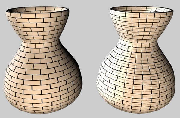
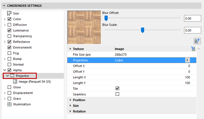
Texture: This is the source image or shader to be projected. You can bring in and project any image or 2D channel shader available to CineRender.
Projection Types:
•Spherical
•Cylindrical
•Flat, Cubic
•Frontal
•Shrink Wrapping
•Spatial
•UVW Mapping
Offset X/Offset Y: Offset of the 2D texture in UV.
Length X/Length Y: Scaling of the 2D texture in UV.
Tiles X/Tiles Y: Tiling of the 2D texture in UV.
Tile: If enabled, the 2D texture will tile in UV the number of times specified in the Tile X and Tile Y parameters.
Seamless: If Tile is enabled, then enabling Seamless causes the tiles to be mirrored so that they tile seamlessly.
Position (X/Y/X): Offset of the 3D texture space.
Size: Scaling of the 3D texture space.
Rotation (Heading/Pitch/Bank): Orientation of the 3D texture space.
The Spectral shader is ideal for prismatic or iridescent effects such as shiny pearls.
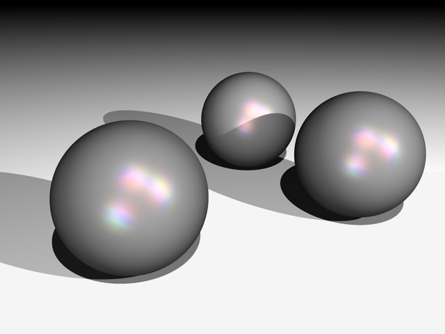
The calculation of this effect takes the camera perspective and the angle between the light source and surface into account. In general, the Spectral shader should be primarily used in a Specular layer (under Layer: Color) in the Reflectance channel.
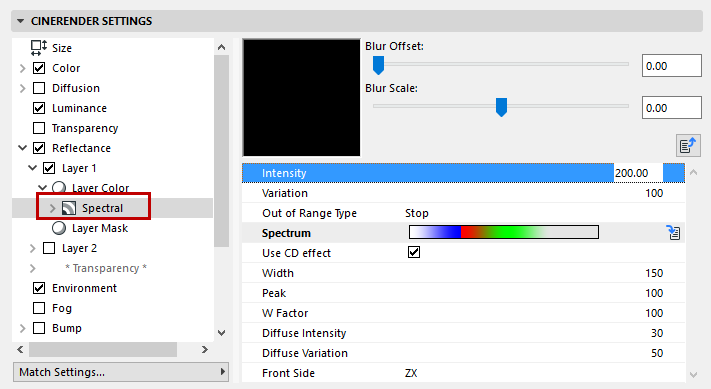
Intensity: Controls the overall brightness of the color reflexes. A value of 0 means no effect at all, while bigger values result in brighter color reflexes.
Variation defines how many times the gradient is repeated within the defined range.
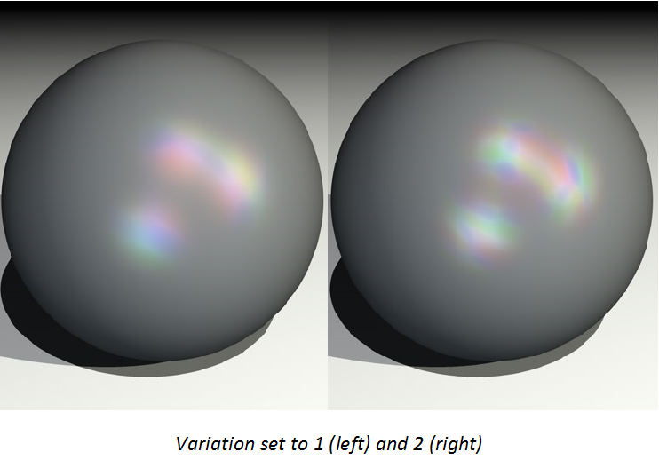
Out of Range Type: In combination with the Variation parameter, Out Of Range Type controls if and how the gradient is repeated. Experiment with the Stop, Mirror and Tiling modes to see the effect.
•With Stop, the gradient is applied once only and the last color is used for the outer areas that are out of range.
•With Mirror, the gradient is mirrored when it is repeated to avoid seams.
•With Tiling, the gradient is repeated according to the Variation value.
Spectrum: The Spectrum gradient defines the colors for the spectral reflexes.
Use CD Effect: If you enable this option, the shader is optimized for cylindrical surfaces and you can render wedge-shaped, prismatic color effects, such as those seen on CD surfaces.
Width: Width defines how far the gradient spreads out.
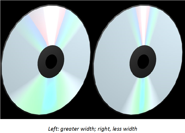
Peak: Normally the entire rainbow colored spectrum is visible only if the angle between the light source and the camera forms a straight line. Increasing the Peak value allows you to generate a larger color spectrum.
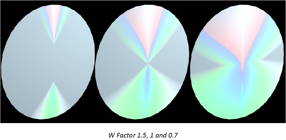
W Factor: Defines the starting point of the prismatic effect, based on the center of the surface. A value of 1 makes the gradient start from the exact center of the surface. Values above 1 offset the gradient away from the center, and values below 1 shift it more towards the center.
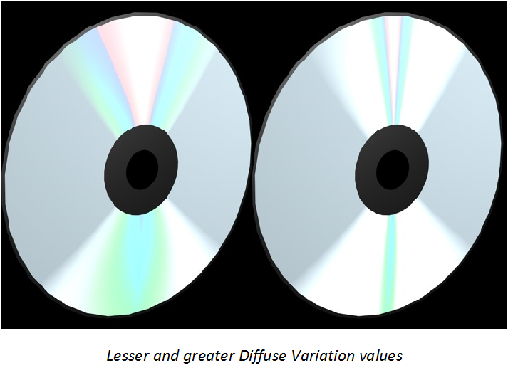
Diffuse Intensity: Diffuse Intensity controls the intensity of the spectral effect. Increasing the value results in overblown colors.
Diffuse Variation: Scatters the spectral effect by bringing in random colors from the gradient.
Front Side: Defines how the spectral gradient is projected onto the surface, with reference to the object coordinate system. If you can’t see the CD effect immediately, you probably need to adjust this parameter.
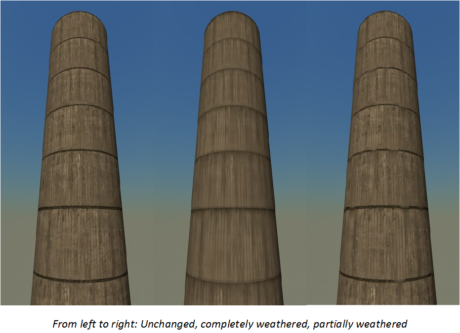
This Shader helps you lend a weathered look to your objects. You can weather a texture in a specific direction, which makes it look as if rain, wind or other factors affected the surface.
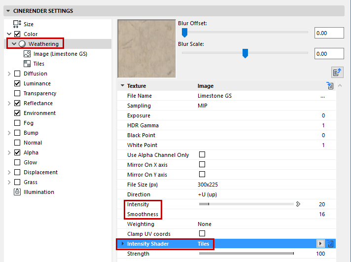
The shader’s Intensity controls the strength with which the texture is smudged, as you can see in the image below in which the value is increased from left to right from 20% (default value) to 50% and 100% respectively.

In addition to Intensity, you can also define how smooth the smudged texture should be. The higher the Smoothness value, the smoother the effect will be and the more realistic it will look. In the image below, the Smoothness is increased from left to right from 4 to 16 (default value) to 32.

Finally, the Intensity shader’s brightness value can be used to define the degree of weathering. An image or a Shader can be used. In the image below, a Tiles Shader was used to create a horizontal line structure.
