Floor Plan/Reflected Ceiling Plan Display (Stair Settings)
Each Stair has two groups of settings, defining display preferences for the Stair Symbol (and its components) on Floor Plan and on Reflected Ceiling Plan.
Note: Switch the Stair’s display by view, using Model View Options. See Stairs: Choose Floor Plan Display or Reflected Ceiling Plan.
Topics on this Page
Display Layouts (Show on Stories)
Choose the stories on which the Stair’s 2D symbol should be displayed.
Layout On (Stair Display On Each Story)
Vary a stair’s symbol display, story by story.
Stair Settings: Symbol Components
Show or hide each symbol component of the Stair. (Overrides the show/hide definitions at Model View options.)
Stair Settings: Symbol Overrides
Apply overrides to the display of the Stair’s entire 2D symbol (lines, pens, fills).
Set Attributes for Each Stair Symbol Component
Set attributes and choose symbol type for any Symbol component (e.g. Break Mark, Walking Line, Numbering).
Display Layouts (Show on Stories)
Use the pop-up to define the Stories on which the Stair’s 2D symbol should be displayed.
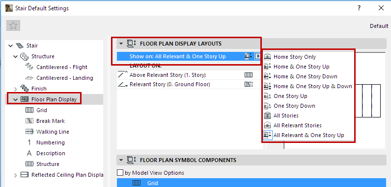
The stories you define (for example, “All Relevant & One Story Up”) are listed in the field below (under “Layout On”).
A Relevant Story is one which the Stair physically intersects. When defining Stories for Stair display, multistory Stairs can have, for example:
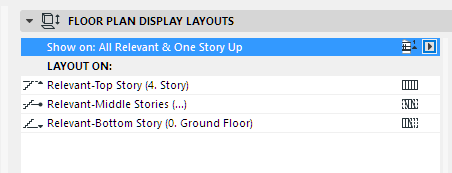
•a Relevant Bottom Story
•one or more Relevant Middle Stories
•a Relevant Top Story
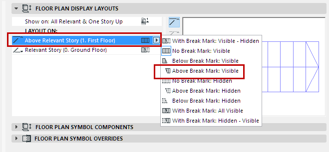
Layout On (Stair Display On Each Story)
Under Layout On: Click on each Story name, then choose how to display the Stair on that story:
•Break Mark: With or without a Break Mark
•Visible vs. Hidden Attributes: To use either Visible or Hidden attributes on the displayed parts of the Stair. The set of attributes (for hidden and visible parts) is defined for each symbol component on its own settings page. See below.
Use the Preview to get an idea of the Stair’s 2D display on each story.
Stair Layout Examples
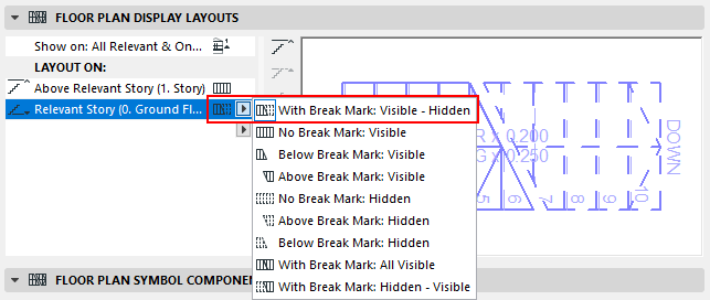
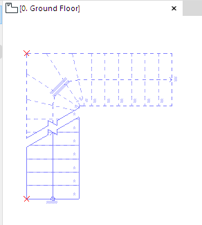
Stair Layout on Ground Floor: With Break Mark, Use Visible Line Type (Below)
and Hidden Line Type (Above)
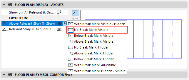
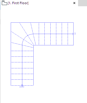
Stair Layout on First Floor: No Break Mark, Use Visible Line Type
Additional Layouts are available for multistory Stairs, with multiple Break Marks.
See also Relevant Story.
On a given Story, you can just display the part between Break Marks.
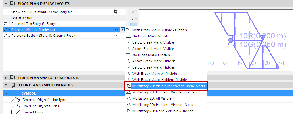
Stair Layout on Middle Stories: Display Between Break Marks Only
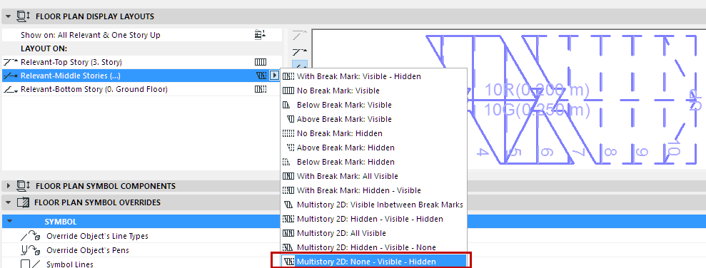
Stair Layout on Middle Stories: None (below Break Line1) - Visible (Between Break Lines)
- Hidden (Above Break Line 2)
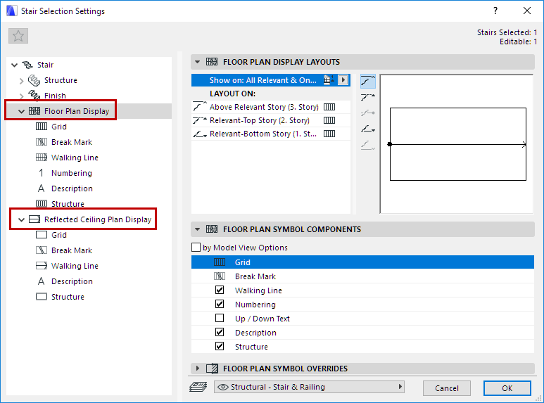
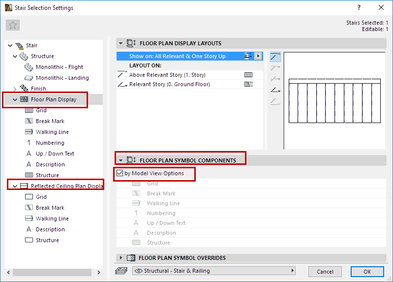
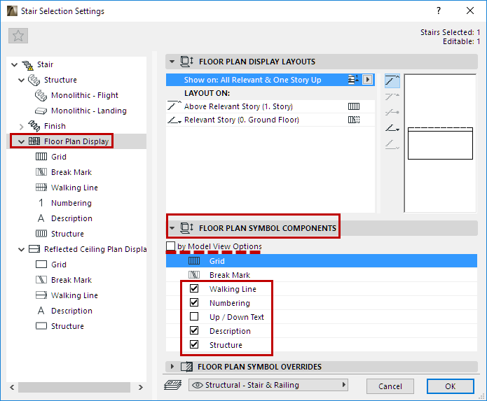
Stair Settings: Symbol Components
These controls are available for both the Floor Plan Display node and the Reflected Ceiling Plan Display node of Stair Settings.
Symbol Components: By Model View Options
Check this to show/hide the Stair’s 2D components as defined at Document > Set Model View > Model View Options.
See Show/Hide Stair Symbol Components (by Model View Options).
Symbol Components: Customize in Stair Settings
Uncheck “by Model View Options” and use the list below to specify which symbols to show or hide. The Grid and Break Mark cannot be hidden.
For example: If you have both an existing and a new Stair in the same view, you may prefer to display the existing one with less detail.
Select that Stair, open its Settings, and uncheck By Model View Options.
From the list below, uncheck the items (e.g. Description, Numbering) that you don’t need to see on that Stair.
Note: This Stair, for which you customized the visibility of its Symbol components, will always appear as you set it, regardless of the current Model View Options setting!
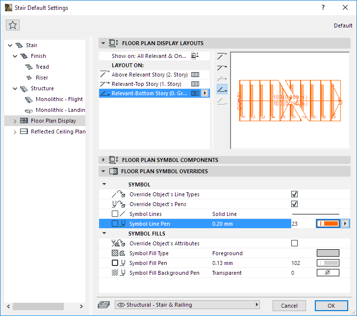
Stair Settings: Symbol Overrides
Available for both the Floor Plan Display node and the Reflected Ceiling Plan Display node of Stair Settings. These settings are independent of Model View Options.
Use them to optionally apply overrides to the display of the Stair’s entire 2D symbol (lines, pens, fills).
•To apply a Line/Pen/Fill override: Check the respective Override box, then select an attribute from the controls below.
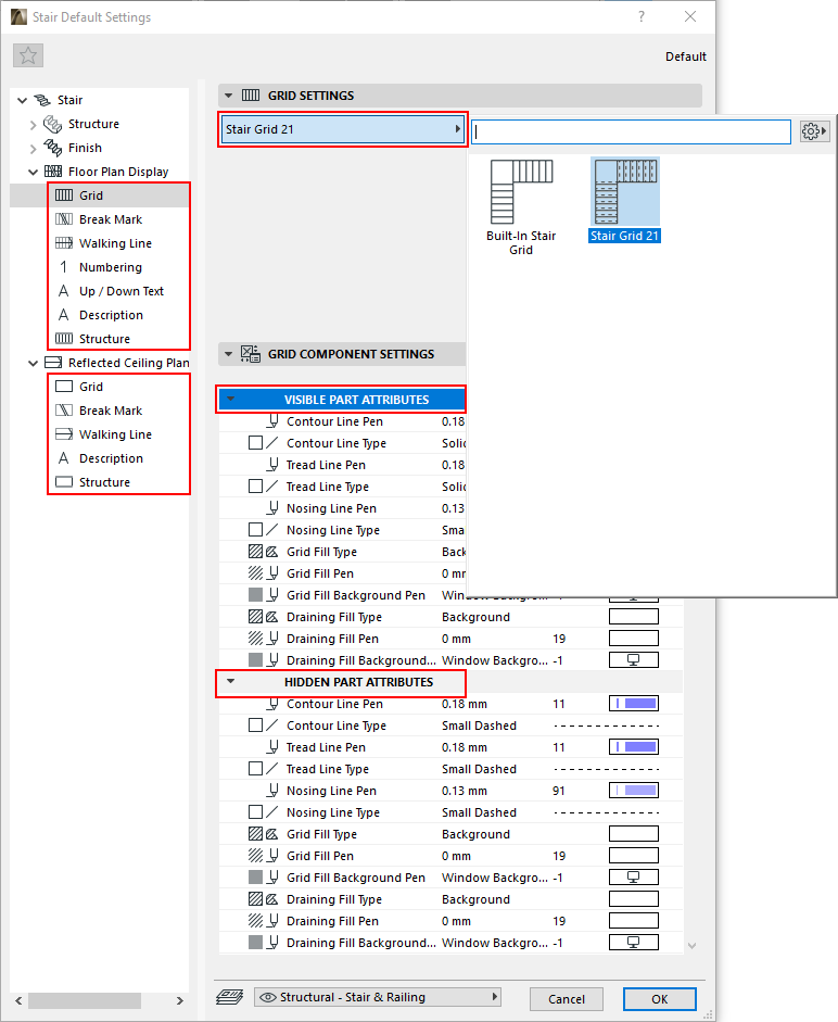
Set Attributes for Each Stair Symbol Component
Available for both the Floor Plan Display node and the Reflected Ceiling Plan Display node of Stair Settings. These settings are independent of Model View Options.
To set attributes, choose a Symbol component (Break Mark, Walking Line, etc.) from the Stair Settings tree structure, to access its settings.
For each Symbol Component:
•Choose a Component type from the pop-up menu
•Set the Component’s attributes in the bottom panel - separately for the Visible and Hidden parts of the symbol, as applicable.
See also Visible Parts and Hidden Parts.
•View the Preview to get an idea of how the component will look.
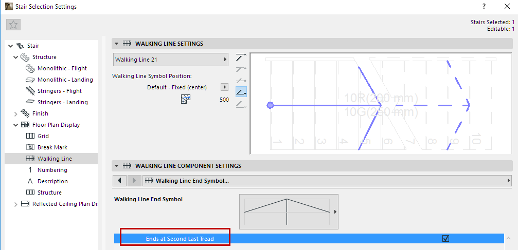
Walking Line Symbol: Position and Display Settings
The Walking Line Symbol Position refers to the Symbol, whose position you can edit manually, either here or in Edit mode.
(In contrast, the Calculated Walking Line, defined in the Geometry and Positioning panel of Stair Settings, affects Tread geometry, and can be edited in Stair Settings only. See Offset Walking Line on Turning (Winder with Equal Goings).
In the Display Settings shown here:
•“Default” setting means that the Walking Line Symbol is at the same location as the Calculated Walking Line, defined in Stair Settings - Geometry and Positioning panel
•“Center” places the Walking Line Symbol at the center of the Stair
•“Custom” means that the Walking Line has been edited graphically to a new position
For details on Symbol editing, see Edit Stair Symbol Components Graphically.
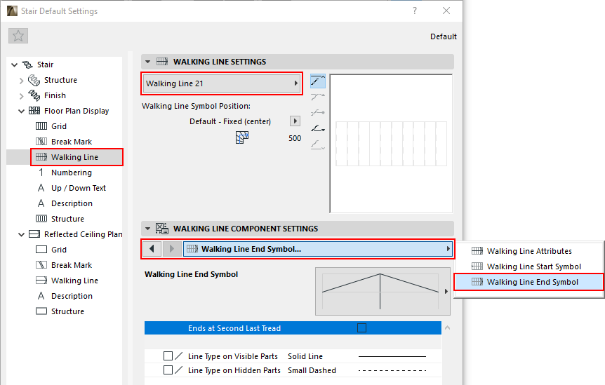
Walking Line End Symbol: End at Second to Last Tread
Check this option to end the Walking Line at the tread before the last one.
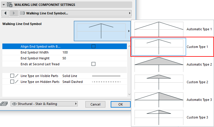
Walking Line End Symbol: Edit Arrow Width/Height
When choosing an End symbol for the Walking Line, note that the “automatic” options mean that the arrow endpoints are fixed, to exactly one Going width.
To edit arrow endpoints, choose a Custom symbol type. You can edit the arrow graphically, too, in Edit mode.
See also Edit Walking Line Arrow and Edit Walking Line Symbol Position.
Break Mark Symbol: Set Position
Use these controls to choose a Break Mark Symbol (e.g. Zigzag), and to set the position and angle of the Break Mark, as well as its attributes.
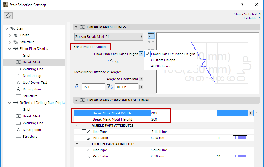
You can edit the Break Mark symbol graphically, after selecting it in Edit mode (Symbol view).
See also Edit Break Mark Symbol.
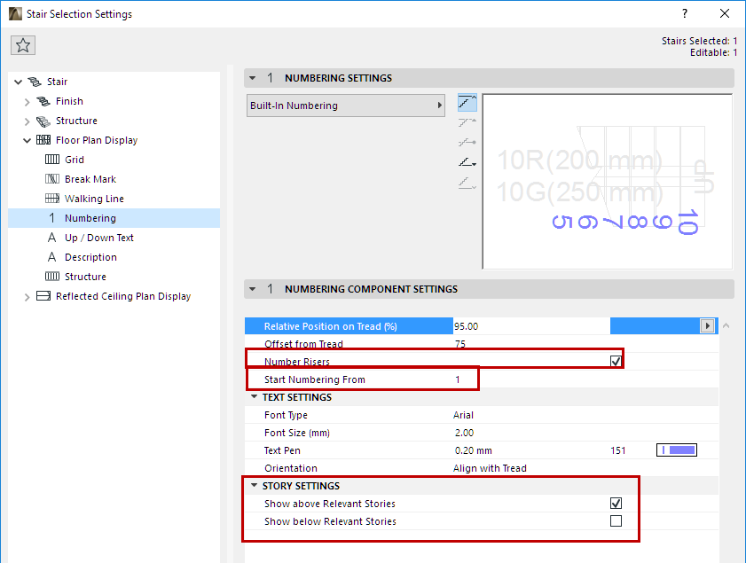
Numbering Symbol: Show Numbers on Stories
Use these controls to set the Numbering preferences for the Stair, including story-dependent display, as needed.
Number Risers: By default, numbering applies to Risers (the “Number Risers” box is checked.) Uncheck this option if you want to number the Treads instead.
You can edit (move or rotate) the numbers graphically, after selecting them in Edit mode (Symbol view).
See Edit Stair Numbering Items
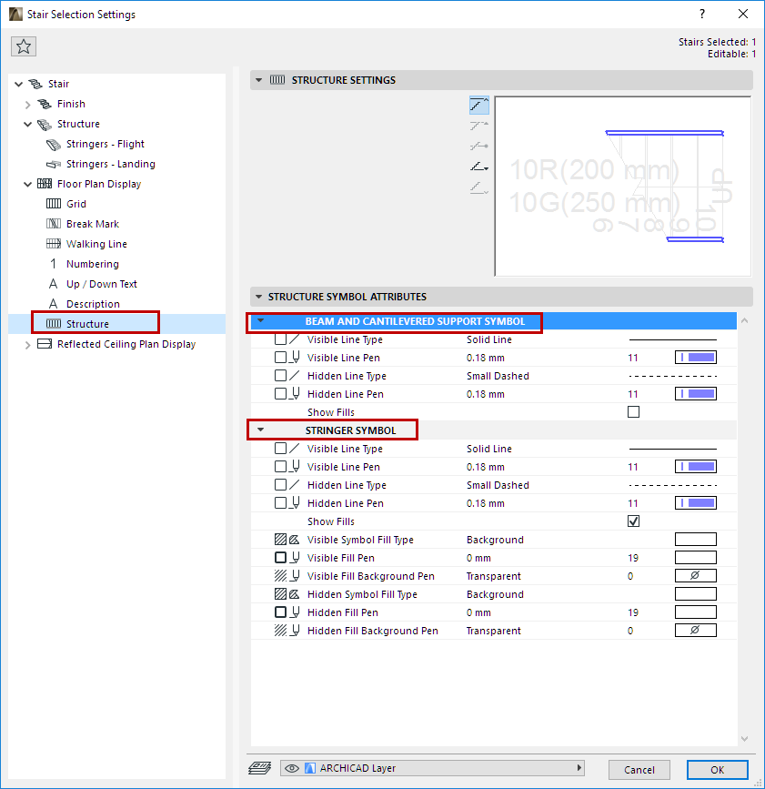
Use these controls to set the 2D display of Stair Structures (Flight and Landing).
Note: Stair Structure components are selected on the Structure node of Stair Settings. (See Flight and Landing Structures.)
•Separate attributes are available for particular Structure types: Cantilever, Beam, Stringer.
•No 2D symbol attributes are available for Monolithic structures.
•Attributes can vary for any structure’s Visible and Hidden parts.