Stair and Railing Floor Plan Display: Model View Options
See also Model View Options for Stairs: Overview.
Model View Options affect the on-screen and output display of Stairs and Railings in 2D and 3D. They set the detail level of Stairs in Sections, Elevations and 3D views, as well as the plan-specific display (Floor Plan or Reflected Ceiling) in 2D.
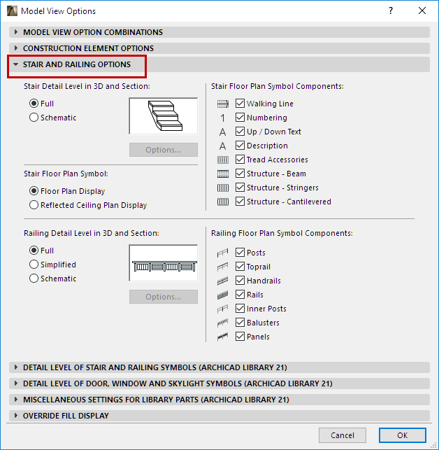
The Model View Options dialog box has two panels with the relevant controls to display Stairs and Railings, by Model View.
This panel is at Document > Set Model View > Model View Options.
Stairs: Choose Floor Plan Display or Reflected Ceiling Plan
Set this control for the Stair Floor Plan Symbol: either “Floor Plan Display” or “Reflected Ceiling Plan Display”.
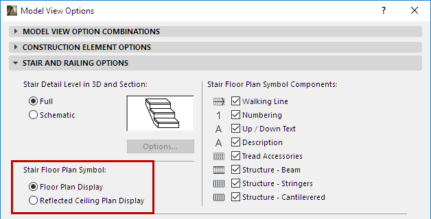
Each Stair (in its own Stair Settings dialog) has two groups of settings, defining display preferences for each of these two symbol types. Switch this Model View Option (Stair Floor Plan Symbol) to control which group of settings to use, by Model View.
See also Floor Plan/Reflected Ceiling Plan Display (Stair Settings).
Show/Hide Stair Symbol Components (by Model View Options)
Use the checkboxes at Model View Options > Stair and Railing Options to control which items should be used in Stair symbols, by Model View.
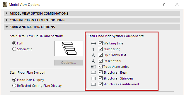
You can override these settings for any single Stair, in Stair Settings.
See Stair Settings: Symbol Components.
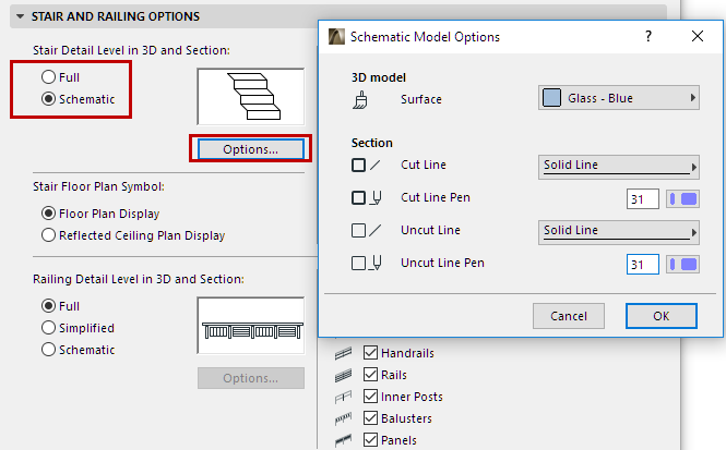
Stair Detail Level in 3D and Section
Choose either Full or Schematic, to define the display and output of Stairs in Sections/Elevations, and in the 3D and 3D Document windows (including Edit mode).
•In Full mode, the complete Stair appears: all 3D sub-elements can be seen in full detail.
•In Schematic mode, a continuous membrane surface is used to indicate the top surface of the steps.
•For Schematic: Click Options to customize surface and line options for Stairs displayed in 3D and Section views.
Railing Detail Level in 3D and Section
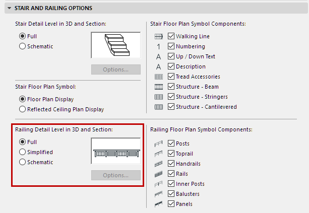
•In Full mode, the complete Railing appears: all 3D elements can be seen in full details
•In Simplified mode, the complete Railing appears: all 3D elements can be seen, but in a simplified view: bounding box of sub-elements are shown.
•In Schematic mode, a continuous membrane surface is shown to indicate the path of the Railing.
Show/Hide Railing Floor Plan Symbol Components
Use the checkboxes to show/hide the Railing’s Floor Plan symbol components.

To show/hide individual Railing Symbols:
1.Click the Custom option on the Railing Settings page. (See Component Visibility and Detail Level.)
2.Then, in the Component Settings dialog, use the Visible Lines and Hidden Lines checkboxes to show/hide the Component’s 2D Symbol.
Note: Component-level visibility settings do not take effect unless the Custom option is enabled in Railing Settings.
Detail Level of Stair and Railing Symbols
This panel is at Document > Set Model View > Model View Options.
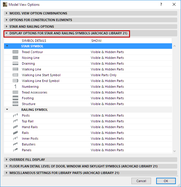
Set the Detail level of each Symbol component:
Note: Components are listed here only if they are checked in the “Symbol Components” list, in the Stair and Railing Options panel above.
•None
•Visible Parts Only
•Hidden Parts Only
•Visible & Hidden Parts
Visible Parts and Hidden Parts
A Stair’s “Visible Parts” represent the Stair’s primary appearance, and are displayed using the “Visible” line type defined in Stair Settings (usually a solid line).
A Stair’s “Hidden Parts” represent the Stair’s secondary appearance, and are displayed using the “Hidden” line type defined in Stair Settings (usually a dashed line).
See Set Attributes for Each Stair Symbol Component.
Visible parts are usually under the Break Mark; Hidden parts are usually above the Break mark.