Railing Settings: Geometry and Symbol Display
The top level page in the Railing Tool Settings hierarchy controls the Railing as a whole.
On this page, you set its Home Story information and any offset, as well as Floor Plan and Break Mark display.
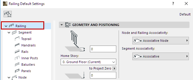
Geometry and Positioning Panel
Home Story
Choose one of the following Home Story settings:
•The current story: The Railing’s Home Story will be the current story, on which it is placed.
•Choose a story to which to link the bottom of the Railing. Click Select Story to bring up the full list of stories in the project, if they are not all shown in the list.
Offset Railing from Home Story
Optionally, define an offset for the Railing bottom from its Home Story. (For associative Railings, the offset field is grey, because the Railing follows the Home Story of its parent element.)
Bottom Elevation [to Reference level]
Note: For associative Railings, this field is grey, because the Railing follows its parent element.
Calculates the current elevation of the Railing’s reference line, as measured from the Reference level (by default, this Reference level is Project Zero).
As with Morphs, the Railing’s Bottom Elevation value shows the current elevation of the Railing’s lowest point. The Railing’s height is measured from this value.
Click the pop-up arrow to change the Reference level, if needed.
Note: Reference levels are defined at Options > Project Preferences > Reference Levels.
Railing Floor Plan Symbol Layouts
Use this panel to define:
•which 2D symbols of the Railing should be displayed
•how to display the Visible/Hidden parts of the Railing symbol on each story
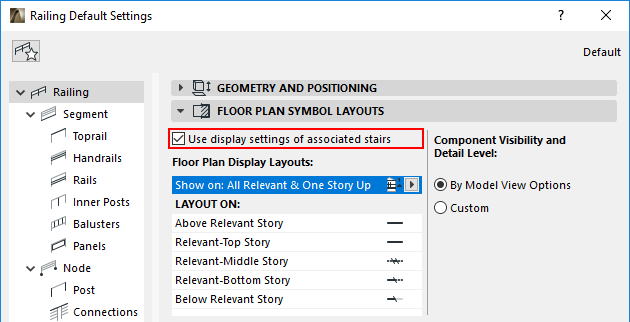
Use display settings of associated Stairs
This box is checked by default. If the Railing is associated to a Stair, then it will be displayed on the same stories as the Stair, using the same Layout options.
These options are defined for the Stair at Display Layouts (Show on Stories).
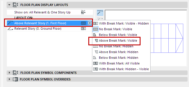
Floor Plan Symbol Layouts (Show on Stories)
Use the pop-up to define the Stories on which the Railing’s 2D symbol should be displayed.
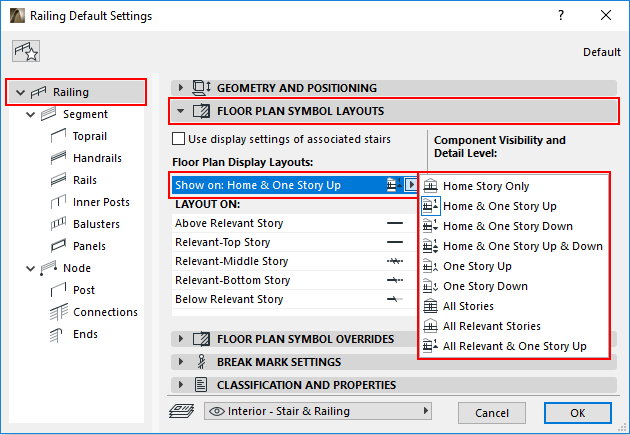
The stories you define (for example, “All Relevant & One Story Up”) are listed in the field below (under “Layout On”).
A Relevant Story is one which the Railing physically intersects.
Layout On (Railing Display On Each Story)
Under Layout On: Click on each Story name, then choose how to display the Railing on that story:
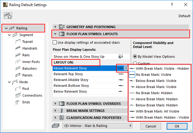
•Break Mark: With or without a Break Mark
•Visible vs. Hidden Attributes: To use either Visible or Hidden attributes on the displayed parts of the Railing. The set of attributes (for hidden and visible parts) is defined for each symbol component on its own settings page. See below.
Visible Parts and Hidden Parts
A Railing’s “Visible Parts” represent the Railing’s primary appearance, and are displayed using the “Visible” line type (usually a solid line).
A Railing’s “Hidden Parts” represent the Railing’s secondary appearance, and are displayed using the “Hidden” line type (usually a dashed line).
Visible parts are usually under the Break Mark; Hidden parts are usually above the Break mark.
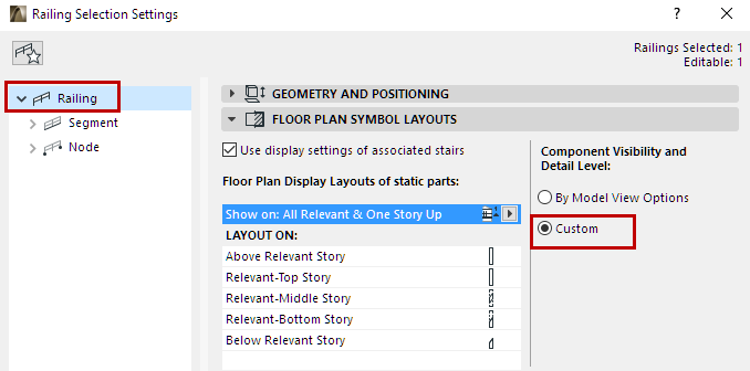
Component Visibility and Detail Level
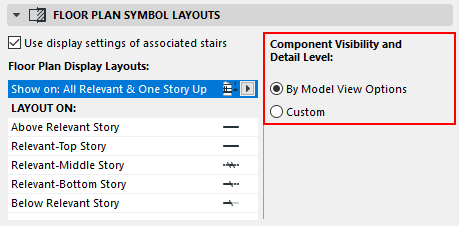
Railing Component Visibility: By Model View Options (Railing Settings Option)
By default, the visibility of Railing components in 2D views is defined at Document > Set Model View > Model View Options.
See Show/Hide Railing Floor Plan Symbol Components.
Alternatively, click Custom to use the component-level settings to show or hide particular Railing components (e.g. the Baluster’s 2D symbol).
In the Component’s settings dialog (e.g. the Baluster’s Component Settings - 2D Representation tab page), use the Visible Lines and Hidden Lines checkboxes to show/hide the 2D Symbol:
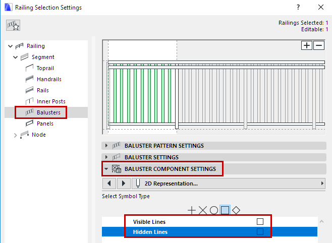
Hide Railing’s 2D Symbol in Component Settings
Note: Component-level 2D visibility settings do not take effect unless the Custom option is enabled on the Railing Settings main page, as described above. (See Component Visibility and Detail Level, above.)
Railing Settings: Floor Plan Symbol Overrides
Use these controls to override all the component-level display settings, and apply a uniform Floor Plan Symbol setting for the following attributes: Line Type, Line Pen, and/or Fill Attributes (Fill Type, Fill Pen and Fill Background Pen).
•To apply a Line/Pen/Fill override: Check the respective Override box, then select an attribute from the controls below.
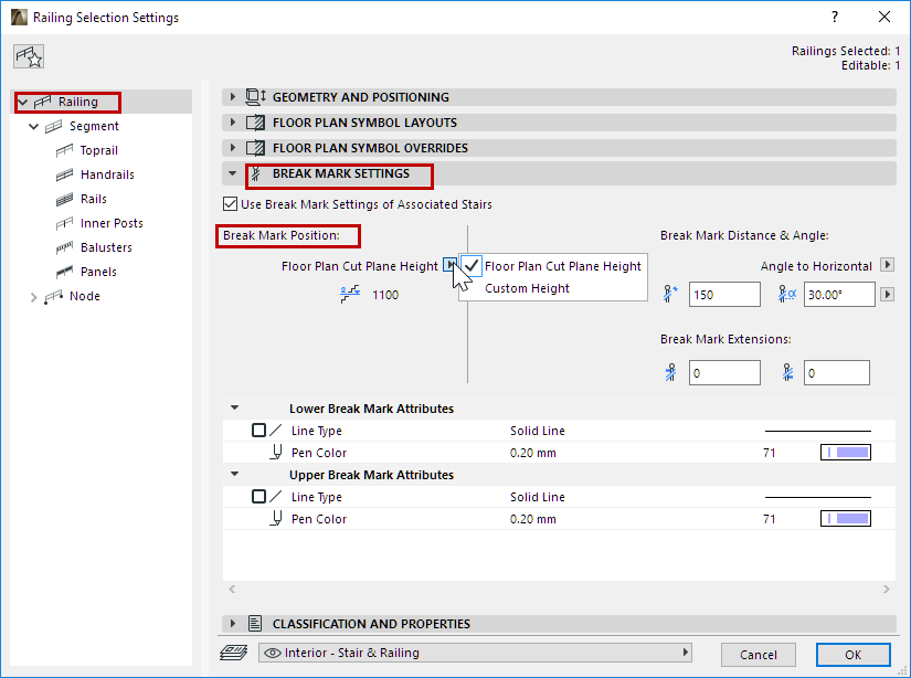
Use these controls to define Break Mark display for the Railing.
Note: For a Railing associated to a Stair: Check Use Break Mark Settings of Associated Stairs to apply the Stair’s Break Mark settings (all those available in the current panel).
•Position: Place the Break Mark at the Floor Plan Cut Plane, or else define a Custom Height using the two fields.
•Distance between the two Break Mark segments; and the segment Angle (defined to Horizontal or to Vertical)
•Extensions to the Break Mark segments
•Attributes (Line Type, Pen Color)