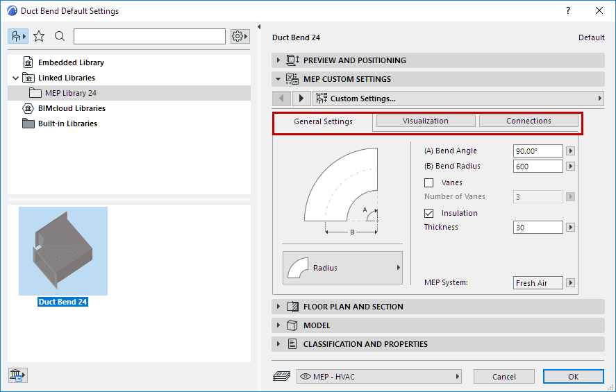
MEP-compatible Library Parts (with smart connections for use in duct, pipe and cabling systems) are found in both the MEP Library and in the regular ARCHICAD Library. Both libraries are loaded automatically as part of the default ARCHICAD template
MEP element Tool Settings are analogous to ARCHICAD’s Object settings.
See also MEP-Compatible Library Parts.
MEP Element Display on Stories
Use the “Show on Story” setting (Floor Plan and Section panel).
The default option for all MEP elements is “All Relevant Stories”.
•Straight segments are displayed as cut on the intersected stories.
•Other (non-straight) MEP elements that intersect stories do not have cut displays - they are shown either on one story or the other.
This has two or three tab pages depending on the object: General, Visualization, and Connection Settings.

General Settings (MEP Element Custom Settings)
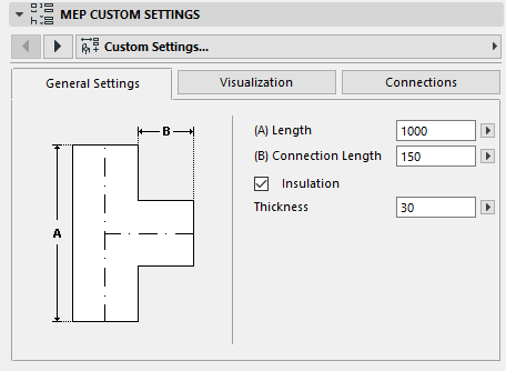
Enter the basic geometry of this MEP object (such as Length of the duct).
Bend Radius
For Bend-type elements. When Routing, you can opt to use this default value (as in element settings), or else the radius defined for the predefined cross-section chosen in the Routing Palette. (See Bending Radius at Routing Options.)
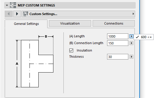
For some MEP objects, the range of possible values depends on other values.
For example, the Length of a Duct Tee (set here in the General Settings tab page) cannot be less than the width of the T-Branch (set in the Connections tab page) that comes off of it.
Insulation
Check this box if you wish to include an insulating layer on the element’s outside surface. Then enter the insulation’s Thickness value in the field below.
MEP System
See Assign MEP System in Tool Settings.
Visualization Tab (MEP Element Custom Settings)
Use the Visualization tab page to assign custom parameters for the display of this element in 2D (plan) and 3D views. Parameters for the 2D symbol are on the left; parameters for the 3D view are on the right.
Typically, you will use these controls if you want to override the MEP System attributes assigned to this element.
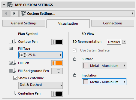
If you have adjusted the surface definition here, the MEP System definition applied to this MEP element changes to “Undefined.”
To revert to the surface defined in the MEP System:
1.Go to the MEP System control (on the General or Connections tab): it is currently “Undefined.”
2.Choose a specific MEP System
3.Return to the Visualization tab page
4.Check the Use System Surface box.
Connections Tab (MEP Element Custom Settings)
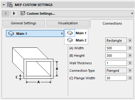
Use this tab page to define the parameters of each of the element's connection ports.
The number of connections on an object varies: a Duct take-off has just one connection port, but a Duct Wye has three.
Use the pop-up to switch among the connections, and edit each of them separately. In this image, we have selected the “Branch” connection from the pop-up on Duct Wye’s Connections tab page.
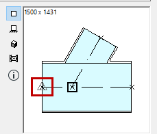
Note that the 2D Symbol object preview on the Preview and Positioning panel gives you feedback (the triangle) on which connection you are editing: in this case, the Branch of the Duct Wye.
Wall Thickness
This is the thickness of the MEP element’s wall.
Connection Type
Choose a Connection Type as applicable. For example, a ductwork element’s connection can either be simple or flanged. If you choose Flanged, enter a value for its width in the field below.
MEP System