Define Settings in Routing Palette
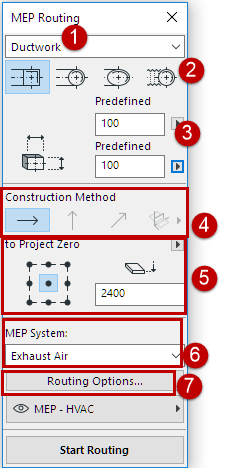
Set the desired options on the MEP Routing palette (Window > Palettes > MEP Routing). These options can be changed in the midst of a routing operation.

1.Choose either Ductwork, Pipework or Cabling from the top dropdown menu.
2.Choose a cross-section geometry preference for the routed elements: Rectangular, Circular, Oval or (Ductwork only) Flexible.
3.Enter a diameter or height/width values for the cross-section, as applicable.
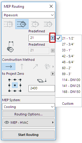
–Enter a predefined height or width from the pop-up, or choose Custom to type in any custom value.
–The list of predefined Duct and Pipe sizes can be edited in MEP Preferences. (Options > Project Preferences > MEP Preferences).

Choose Predefined Pipe Diameter
4.The Construction Method is not editable until after you start Routing. All new routes are set to “Constant Elevation” (the horizontal arrow). Once you start routing, you can switch to another routing elevation as you proceed. (See Vary Elevations During Routing.)
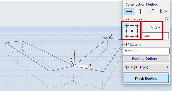
5.Reference Line location/Elevation: Choose one of the nine points in the Routing palette to define the location of the reference line of the routed elements, at the given elevation. (This reference line is relevant only during a Routing operation, and indicates the anchor point of the routed elements when you click on screen to place them. You can switch this location en route as needed.)
In this image, the reference line during routing runs along the top left corner of the duct, as viewed in the direction of routing.

6.Choose an MEP System attribute for this Routing operation.
7.Adjust additional Routing Options as needed. (See Routing Options.)
8.Choose a Layer on which to place the routed elements.