Miscellaneous Settings for Library Parts
To access this panel, go to Document > Model View > Model View Options.
•This panel and its contents depend on the libraries you have loaded. (You may have multiple panels, one for each loaded library in your project.)
•Library objects located in that specific library will be globally displayed according to the Model View Options set here.
•Options will be applied only to objects whose GDL script is programmed to allow for this.
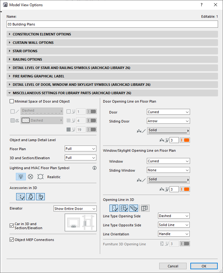
In the INT version of Archicad, the panel looks like this:

Show Minimal Space of Door and Object
Check this box to show the objects’ and doors’ minimal space on the Floor Plan by displaying a contour and fill corresponding to the minimal space parameter. Choose options for the contour’s line type and pen, and for the fill type/pen/background.
Minimal Space contour/fill display is shown for all doors and objects which have a defined Minimal Space parameter.
•For Doors, set these parameters in the Minimal Space tab page of Door Settings (Custom Settings panel).
See Minimal Space.
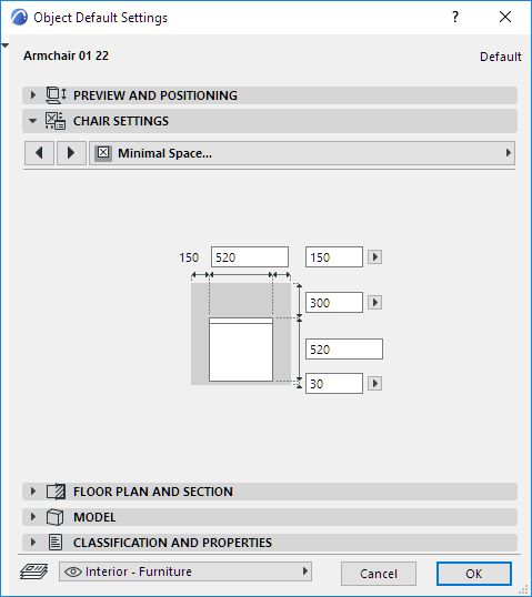
•For Objects, use the Minimal Space parameters in Object Settings.

Object and Lamp Detail Level
Set the Detail Level on Floor Plan:
•Full, Medium, or Low
and in 3D Projections:
•Full, Simplified or Schematic
Objects and Lamps use the detail level settings defined here by default (By MVO). For a specific object/lamp, if the control is available, you can override its detail level in Element Settings (use the 2D or 3D Representation controls)
See 2D and 3D Representation of Objects.
Lighting and HVAC Plan Symbols
Choose one of the options for displaying the Floor Plan Symbols of Lighting and HVAC objects (e.g. ceiling lamp, smoke detector, air diffuser) in the project.
•Realistic
•Electric
•Reflected Ceiling Plan
Accessories in 3D
Click the toggle buttons to show or hide these types of accessories in 3D:
•Object Knobs in 3D
•Object Taps in 3D
•Door Handles and Knobs in 3D
Elevator Car
Set options for the display of the Elevator Object’s Car component:
•Show/Hide Car in 3D and Section/Elevation
•Show/Hide Elevator Doors in Floor Plan/Section, or display just the opening
Object MEP Connections
Elements compatible with MEP Modeler include Connections to enable connection to any object in an MEP route.
Use this checkbox to show or hide these Connections.
Doors/Windows/Skylights Opening Line on Floor Plan
•Opening Line style: Curved or Straight
•For Sliding Doors and Windows: None or Arrow
•Line Type and Pen for the opening line
Opening Lines in 3D Projections
Click the toggle buttons (Door, Window, Skylight) to show or hide their opening lines in the 3D window.
•Choose lines (dashed, solid, dotted) for the opening lines on the opening and opposite sides.
•Choose either Handle or Hinges to set the opening lines’ orientation.
Note: This option is scale-dependent (generally, opening lines are not displayed at small scales).
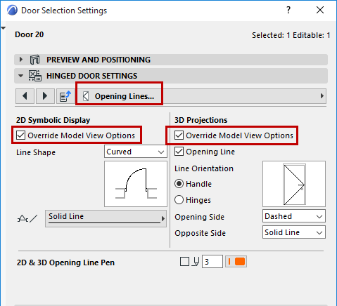
Override Model View Options for Particular Door/Window
Model View Options affect all Doors/Windows in the view. To override Door/Window opening lines settings for any particular Door/Window, use the Opening Lines tab page of the Custom Settings panel.
See Opening Lines (Door/Window).
