Instead of connecting Structural Analytical Members using Adjustment
Rules, it can make more sense to keep the elements separate. (For example, if adjusting 2D
Members to each other would move one of the planes outside of its element.)
In such a case, you can use Structural Links instead, to indicate how
applied loads are transferred between the Structural Members.
The Structural Link can be a 1D Link or a Surface Link, depending on
the situation.
Note also:
A 1D Link with zero length can be placed at a point - for example,
to link two bracings while keeping them as independent elements.
A Surface Link having a length dimension but zero width can be
placed between two edges.
They are placed only on 1D and 2D Members of the Structural Analytical
Model - you cannot use Structural Links with physical model elements in Archicad.
A Structural Link necessarily has two “parent” Members. If either
Member is not part of the current Structural Analytical Model view (due to Renovation
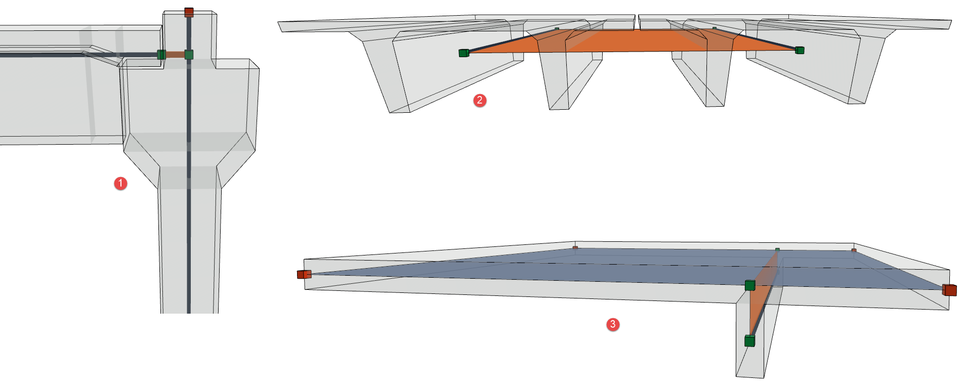
Status), the Link element also disappears.Figure 1. 1: Prefab Reinforced Concrete elements with cantilever connection; 2: Precast
panels modeled with Beams; 3: High rib (Offset adjustment not allowed)
There are two ways to create a Structural Link:
Use the Structural Link tool
Use the Create Links dialog
The resulting Structural Links are associated to the connecting Members:
If you move the element, the link moves with it.
To show or hide these elements in 3D: Use View > Elements in 3D View
> Filter and Cut Elements in 3D
Example: Use Structural Link Tool
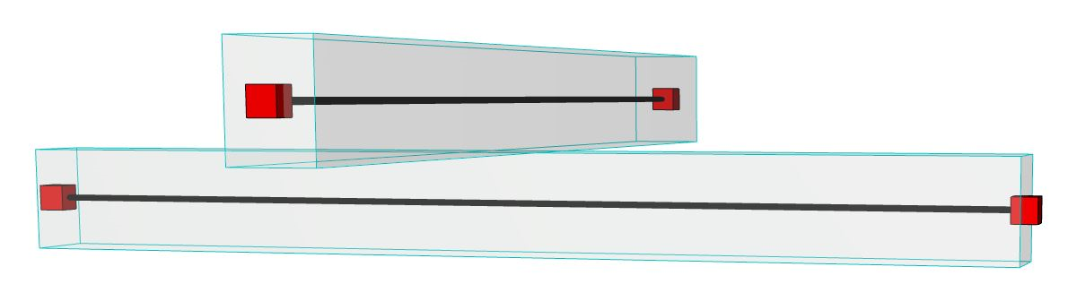
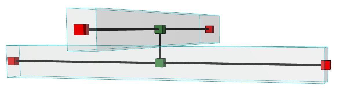
In this example, the user wants to transfer the forces from the upper
Beam to the lower one. The two Beams should be “connected” through an analytical link.
Activate the Structural Link tool
from the Toolbox
from Design > Structural Engineering Tools > Structural
Link
From the Info box, choose 1D Link as the Geometry method.
Choose Rigid as the link type.
Click twice - once on each 1D Member - to create the link between them.
Note:
If you move linked elements, the link remains connected to the
originally clicked point.
Use space + click to automatically create a Structural
Link that is the shortest distance between the two Members. If you later move these
linked elements, the associated Structural Link will be adjusted as needed to be the
shortest link possible.
Example:
“Create Structural Links” Command
Use the Create Structural Links function to create several link
types between different elements. The function works on selected elements, or (if nothing is
selected) the entire Structural Analytical Model.
Important: This function affects only elements that are
connected at their cores.
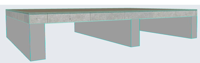
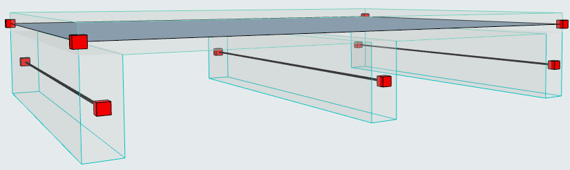
In this example, the Slab is supported by Beams of significant height.
It is not structurally realistic to use the offset adjuster in Generation Rules. The Beams
should retain their structural axis at their default location at the center of gravity.
We will add Structural Links to indicate load transfer from the Slab to
the Beams.
Select the elements to be linked.
Activate Design > Structural Analytical Elements > Create Structural
Links.
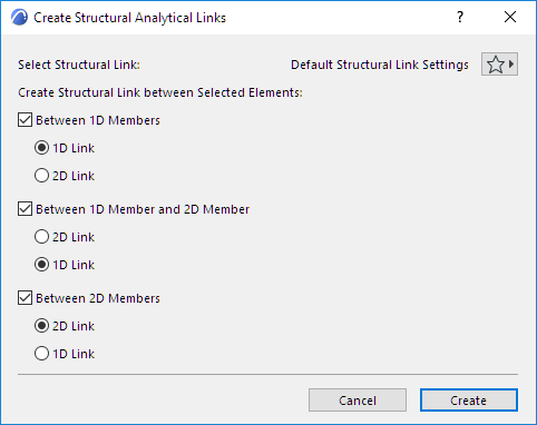
In the appearing dialog, set options:
In this case the link should be Between 1D Member and 2D
Member (Beam and Slab), and the link should be along the full Beam length (2D
Link).
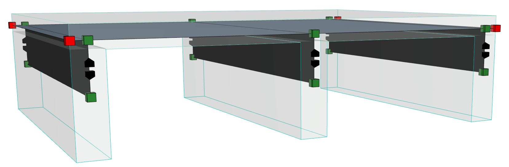
Click Create. The 2D Structural Links appear:Figure 2. 2D Structural Links Between 1D (Beam) and 2D (Slab) Members
As expected, the structural axes remain at their original position
(center of gravity), but new nodes now appear on the Slab plane, indicating where the
structural links are connected to the Slab.
When the Structural Analytical Model is exported, the structural
analysis software will interpret that the loads imposed on the Slab will be transferred
through the links to the Beams.