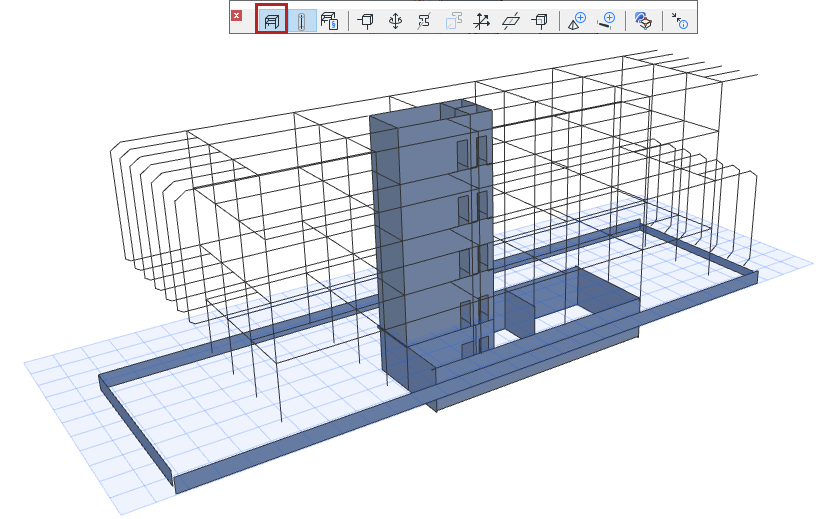
The Structural Analytical Model can be displayed in Floor Plan, Section
windows, and 3D views.
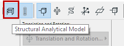
Use the Structural Analytical Model toggle
in the Structural Analytical Model Toolbar
in the View menu
The Show/Hide status is specific to each view (if it is on in one view,
it can be off in another view).
Important: Archicad elements are part of the Structural
Analytical Model only if they have certain geometric and property settings. See Elements of the
Structural Analytical Model.
Show Transparent
Physical Model
If the Structural Analytical Model toggle is on:
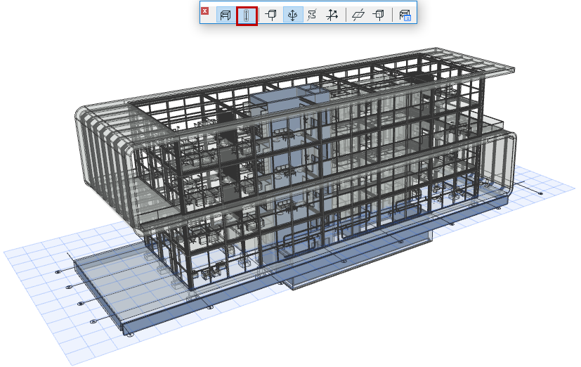
Use the Transparent Physical Model toggle to also display the Physical
Model in transparent form, in the current view:
Show Components of
Structural Analytical Model
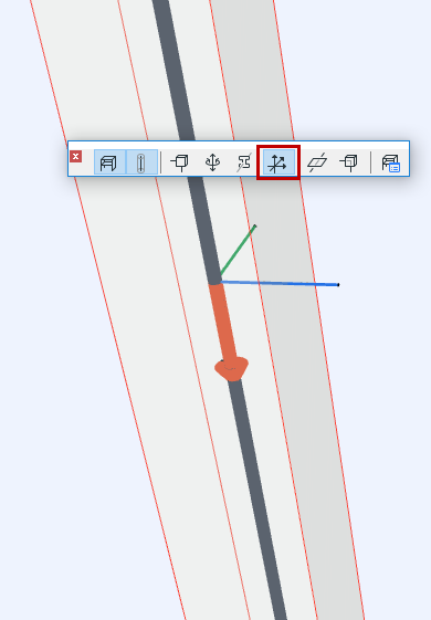
Use the following additional toggle controls to show or hide Structural
Analytical Model components. The controls are available from:
Structural Analytical Model Toolbar
View > Structural Analytical Model Options
View > Elements in 3D View > Filter and Cut Elements in 3D (for
Structural Support and Link elements)
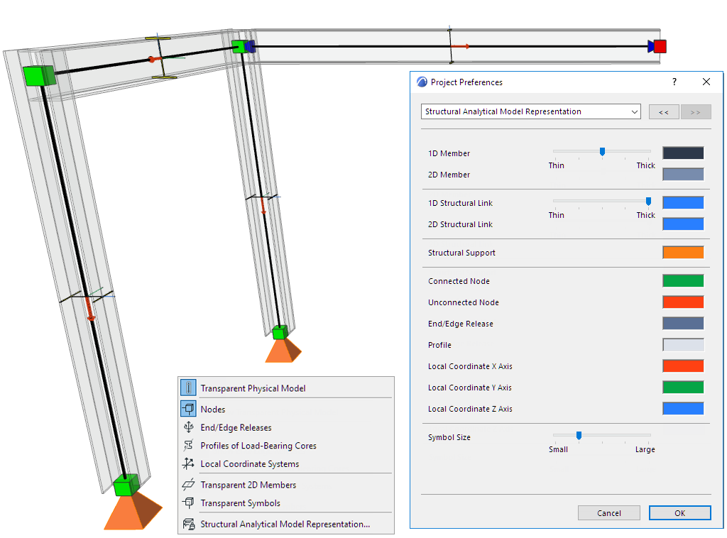
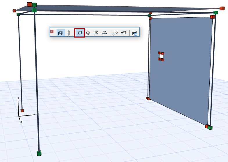
Display nodes at ends and corners of the 1D and 2D Members.
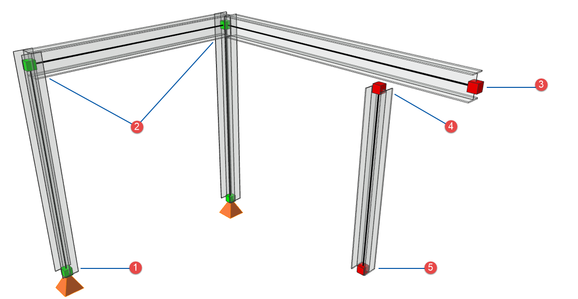
Node Connections: Color
Feedback
By default:
A green node represents a correct connection point or intersection
between joined Analytical Members
A red node represents a point or end that is either free (no
connection needed), or unconnected/unsupported:Figure 1. 1: Supported, 2: Connected, 3: Free end (Cantilever), 4: Unconnected, 5:
Unsupported
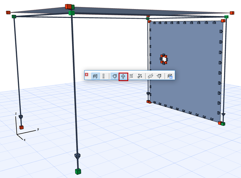
Show End/Edge Releases
Use this toggle to display their symbols in the Structural Analytical
Model.