Model View Options for MEP elements
To access this panel, go to Document > Model View > Model View Options.
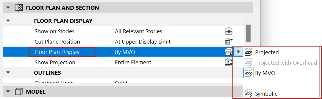
These MEP options control the appearance of MEP elements on the Floor Plan. For these settings to take effect, each element’s Floor Plan display option (at Element Settings) should be set to “By MVO”. (See Display of Route Element: Floor Plan and Section, Model Display ).
In the MEP Options panel: Choose how to display each MEP route and element type: projected, full (with insulation), simplified (without insulation), or schematic
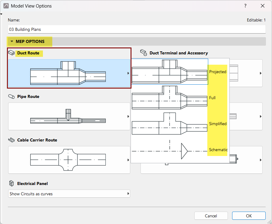
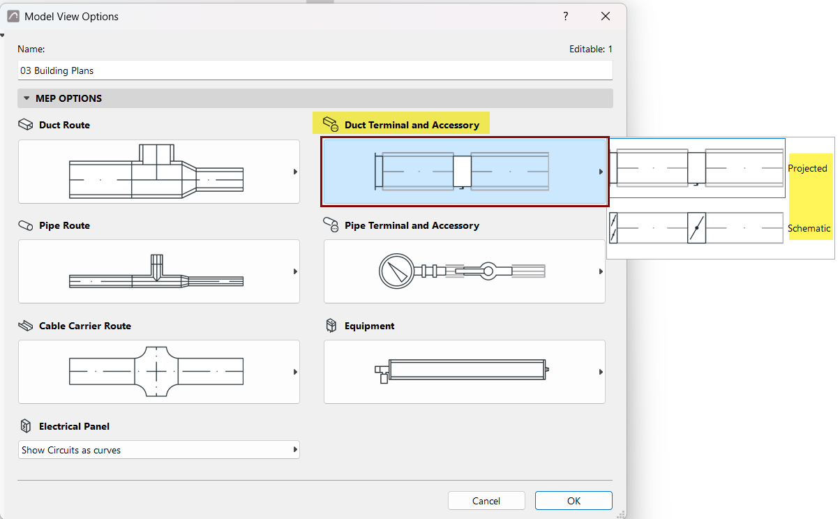
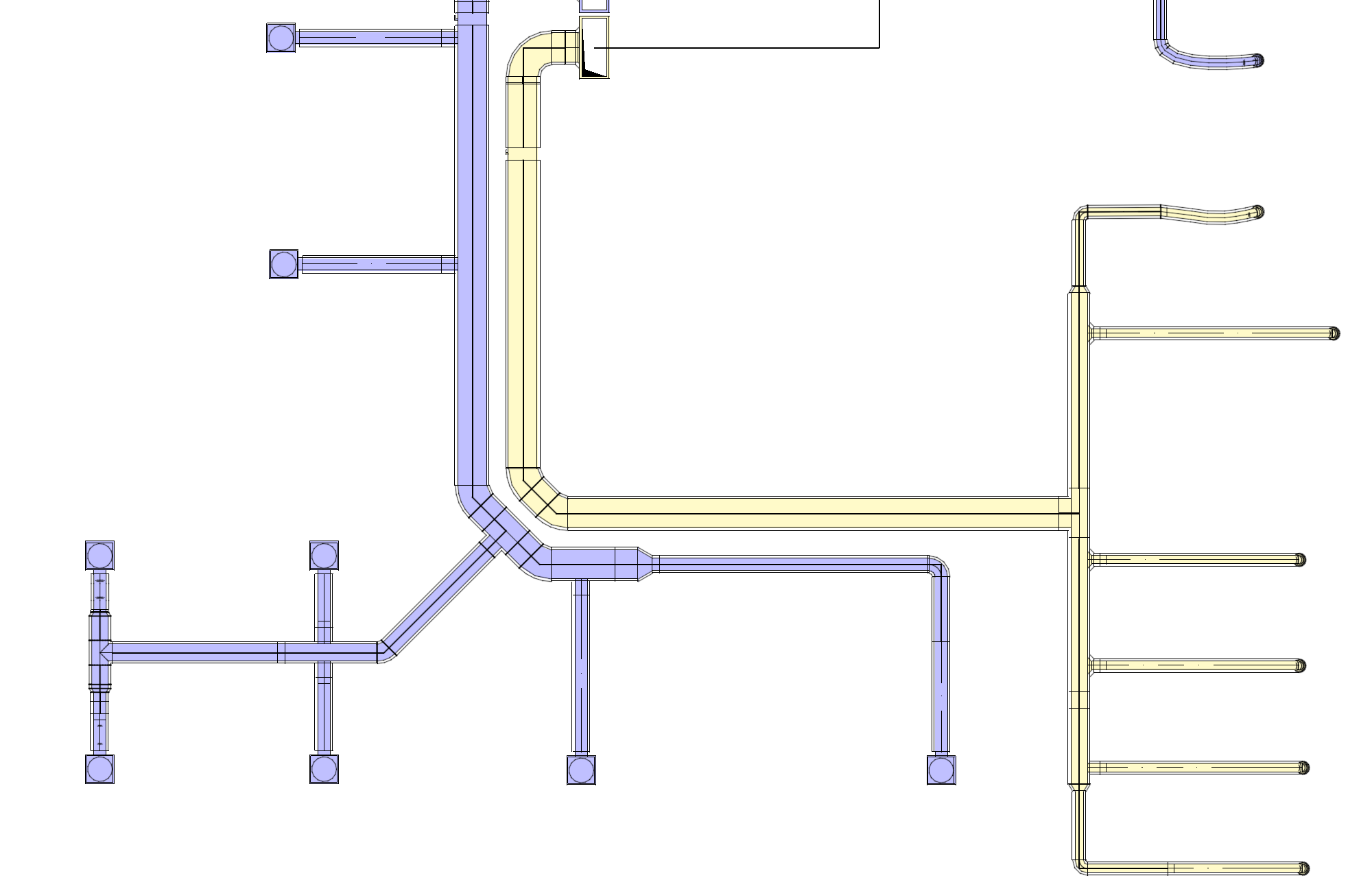
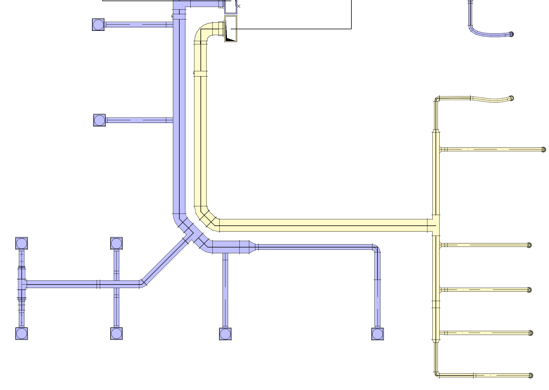
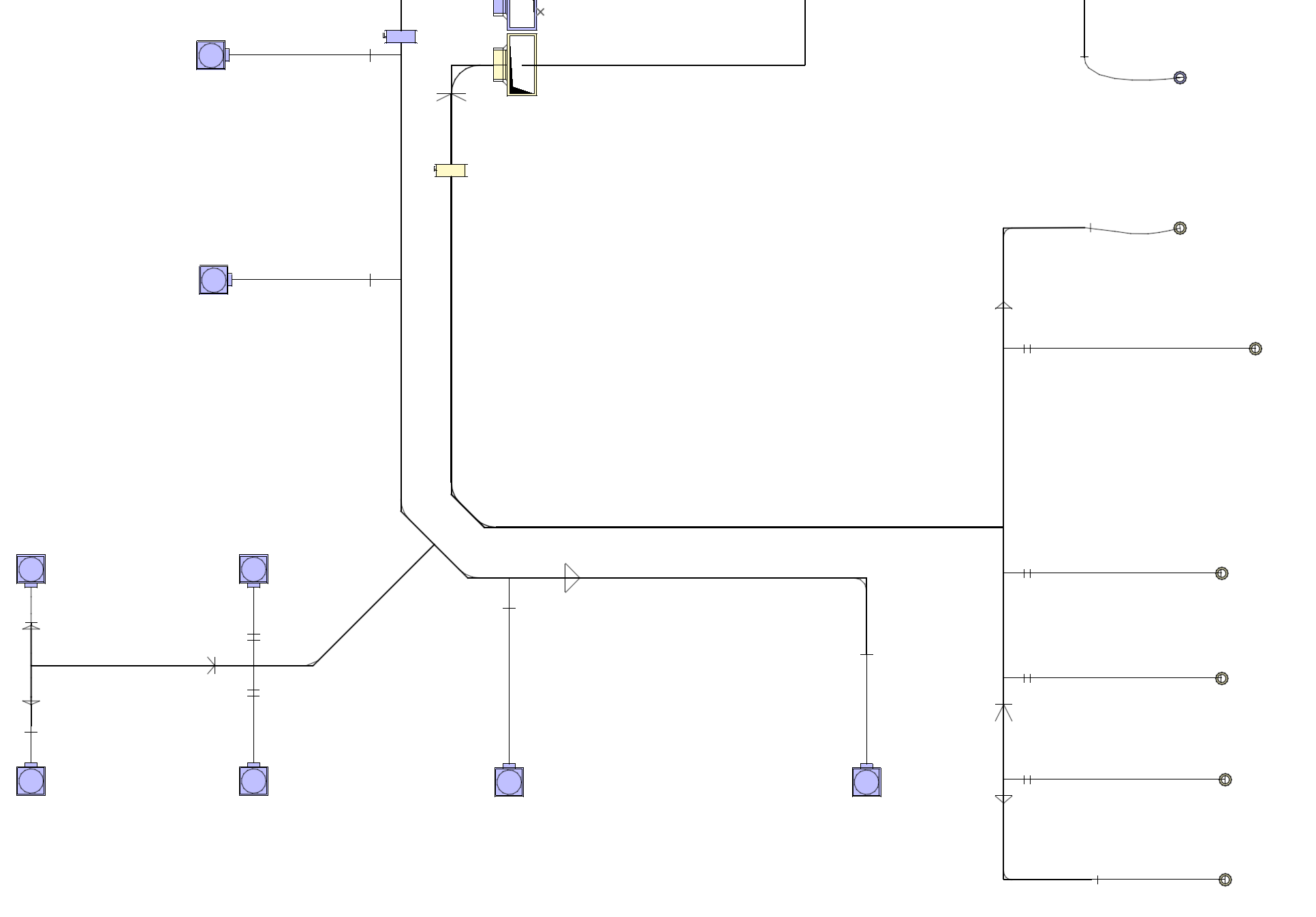
For Model View Options to take effect for any route, make sure its Floor Plan display option (at Route Settings) remains set to “By MVO”.
You can also override this setting, choosing Projected or Symbolic for any individual route. See also Floor Plan Display
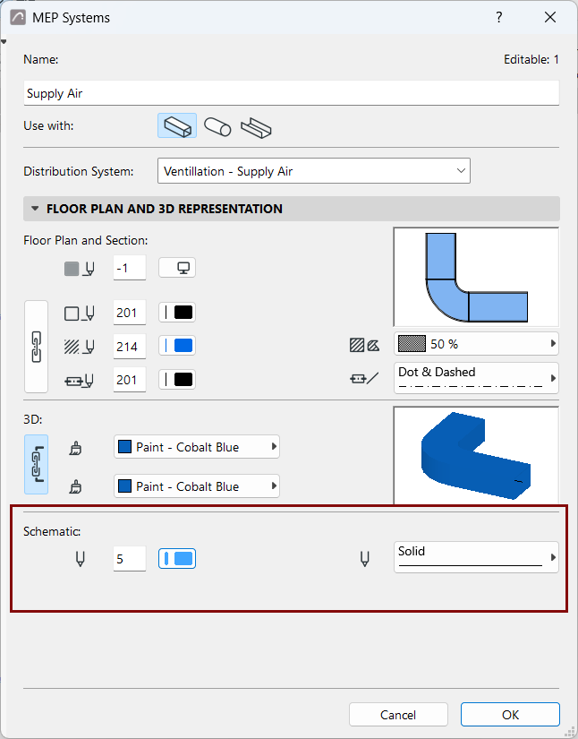
For Schematic display, define line colors by System, using MEP Systems dialog.
Electrical Model View Settings
See also Create custom MEP symbol.