
Physical Model Check Parameters
This check identifies any two intersecting structural elements whose cores do not connect to each other.
In this example:
The Wall intersects the Slab only as far as the Slab finish: the cores are not connected!
This problem affects the Structural Analytical Model, because if the element cores are not connected, the Adjustment Rules cannot take effect, and the 2D Members remain disconnected.


Notes:
–All elements with a Basic Structure have a core, so they are always considered in this check
–Complex Profiles and composite structures are considered only if they include at least one component that is defined as “Core”
–All elements that contain a core are considered (not just the load-bearing elements)
Another Load-Bearing Element closer than
This check identifies any pair of load-bearing elements which do not intersect at all, yet are closer to each other than the given tolerance value.
This situation is probably a modeling error, as shown in this image: a tiny gap exists between the Slab and the Wall.

Elements with inadequate Core dimension ratio
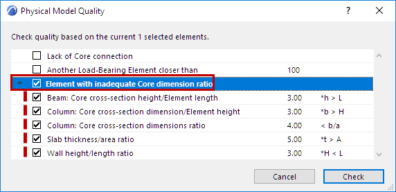
Use this checkbox to turn this group of parameters on or off (or deactivate any parameter individually).
Each parameter examines the ratios of certain core dimensions of Beams, Columns, Slabs and Walls, and checks if the result ratios are within the defined range.
If the ratio is not within the defined range, these elements are identified as “Element with inadequate Core dimension ratio” in the Model Check dialog.

•All core-containing elements are considered, regardless of their Structural Function (not just the load-bearing elements).
•The checked dimensions refer to the core part of the element.
–For example, for a composite Slab that is 300 mm thick (200 mm core component plus 100 mm of insulation and plaster skins), only the core thickness of 200 mm is considered as part of the check.
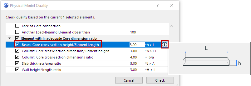
•To see an illustration of the checked ratio: select an item, then click the Info button.

To See Illustration: Select Parameter, Click “Info”
Tips for Using “Inadequate Ratio” Parameters
This set of parameters in the Physical Model Quality Check dialog are based on the Eurocode standard for concrete structures. (See below for a brief description of each.)
For example, a Column whose cross-section width and height are out of proportion might be considered as a 2D Member rather than a 1D Member.
Results listed in the Model Check dialog are not necessarily errors. However, to promote consistency, you can use these “inadequate ratio” parameters to fit your specific workflow and the requirements of the receiving software. For example:
•Project team members can agree to model certain structures (such as a parapet) with a Wall rather than a Beam, or vice versa.
•Project team members can agree to model the building-length Walls using separate segments, rather than a single extra-long Wall.
•Use the Model Check to find any discrepancies
Check any of the following parameters related to inadequate core dimension ratios:
Beam: Core Cross-section height/Element length
Ratio of the Beam’s total length to its (core cross-section) height.
For example: if the Beam is “too tall” compared to its length (based on the given relation values), then it is listed in the Model Check Report.
The rules of the structural analytical software might consider this element as a 2D Member (like a Wall) rather than a 1D Member, or as a Column rather than a Beam.
Note: the “Wall height/length” parameter (described below) checks for the inverse of this situation.

Beam “Too Tall” Compared to Length
Column Dimension Parameters
The next two parameters check Column dimensions in two ways:
Core cross-section dimension/Element height
Core cross-section dimensions ratio
Notes:
–These parameters consider only the parts of the column defined as “Core”.
–If the Column has a Veneer: the Veneer thickness is considered if that Veneer component is defined as “Core” (in Column Settings, “Segment” page.) If the Veneer is defined as “Finish” or “Other”, it is not considered.
Slab thickness/area ratio
Compares Slab core thickness to the Slab area.
If this ratio is greater than the given value (if the Slab is too “thick” compared to its area), it is listed in the Model Check Report.

Slab “Too Thick” Compared to Area
Wall height/length ratio
Ratio of the Wall height to its total length.
For example: if the Wall is “too tall” compared to its length (based on the given relation values), then it is listed in the Model Check Report.
The rules of the structural analytical software might consider such an element as a 1D Member (like a Beam) rather than a 2D Member.
Note: The “Beam height/length” parameter (described above) checks for the inverse of this situation.