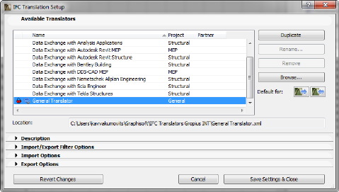
Importing and exporting model data using IFC takes place according to the settings of the translator you are using. ArchiCAD provides predefined, factory-default IFC Translators, but you can define your own. IFC Translation Setup command (File > File Special > IFC 2x3) allows you to view or modify translator settings, or to create new translators. The following is a description of the settings found in the IFC Translator Setup dialog box:
By default, you will see the predefined translators (offered for structural, MEP and general connections) shipped with ArchiCAD. Any newly created translators will also be listed here. The program’s default translators for import and export are distinguished by a blue arrow symbol; these default translators will be shown when you execute the import or export commands. You can define any selected translator as the default (for export and/or import) by using the “Default for” icons.
The only way to create a new translator (or modify a locked translator) is to first duplicate an existing one (use the Duplicate button). Next, use the Rename command to give the copy a new name. The newly renamed translator will contain the same settings as the one you duplicated, but you are free to change any of the settings.
Each translator is stored in an .xml file; these files can be exchanged among ArchiCAD users, and imported into ArchiCAD projects using the Browse option. The “Location” field below shows the path of the selected translator’s .xml file.
Use Delete to remove a translator you don’t need from this list.
Notes:
•With Browse you can re-load the translators (removed before) back to the list.
•Modifications to translator settings take effect when you click Save Settings & Close.
•If you want a customized translator to revert to its original, factory-default settings, first find the original translator file in the \Program Files\GRAPHISOFT\ArchiCAD version\Defaults\IFC Translators folder (Windows platform) or /Applications/GRAPHISOFT/ArchiCAD version/Defaults/IFC Translators folder (MacOS platform), then use this file to overwrite the current translator, found at the place given in the Location field.
•A translator that is locked cannot be modified; the settings described below cannot be changed in this case. However, if you duplicate a locked translator, you can change its settings.
This field is a short textual description of the translator currently selected in the list. This field is empty for a newly created translator, but you can enter any text you like.
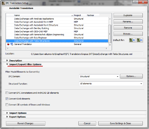
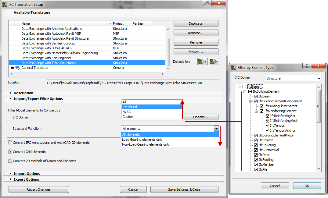
Displays the default element-type filter for the selected translator. Use the IFC Domain to filter according to the following criteria for IFC import and export: “All” will include all elements from the model; “Structural” will include only the structural building elements (IfcBuildingElement); “HVAC” will include only the mechanical elements (IfcDistributionElement). To see the exact composition of each Domain filter, click Options; modifying these options will create a “Custom” filter.
•Structural function
Use this as an additional (element-level) filter for export and import purposes, which will take into account the elements’ Structural Function classification at export and “LoadBearing” IFC Property at import.
See Structural Function.
-“All elements” will not take the elements’ Structural Function classification into account.
-“Load-Bearing elements only” means that only those elements classified as “Load-Bearing Element” will be exported from ArchiCAD to IFC; and only those elements having the IFC Property “LoadBearing Element” with “True” value will be imported from the IFC file to ArchiCAD.
-“Non-Load-Bearing elements only” means that only those elements classified as “Non-Load-Bearing elements” will be exported from ArchiCAD to IFC; and only those elements having the IFC Property “LoadBearing” with “False” value will be imported from the IFC file to ArchiCAD.
Notes:
-If no Structural Function classification has taken place in the ArchiCAD project, or if you have not finished the classifying process in ArchiCAD, then you should choose “All Elements” here: either of the other two settings (“Load-Bearing elements only” or “Non-Load-Bearing elements only”) can result an empty IFC file, or one that is missing elements you might need.
-The default Import/Export Filter Options set here can be overwritten during the export/import process using the Model Filter options.
See Model Filter.
•Convert IFC Annotations and ArchiCAD 2D elements
If you check this box, the export process of the following 2D elements is allowed: Texts, Labels, Fills, Lines, Arcs, Circles, Polylines, Splines and all dimension types.
However, the inclusion of 2D elements in the exported file is also affected by the “Export” option set in the export IFC dialog boxes.
-If a 3D view is currently active, the 2D elements can be included only if the “Entire project” option is used.
-If a Floor Plan is active, the “Visible” option means only the visible 2D elements will be saved, and “Selected elements only” means that only the selected 2D elements will be saved.
These 2D elements will show up in the IFC scheme structure as IfcAnnotation. Dimensions will be exploded into lines and texts, since the IFC 2x3 standard documentation does not include a dimension element.
During import, all IfcAnnotation-type elements (including exploded dimension elements) of the IFC file will be imported into ArchiCAD and converted into 2D elements (texts and lines) by checking the box.
If you check this box, the export process will include the Grid Elements and the grid members of the Grid Systems (Design) in the IFC file.
However, the inclusion of grids in the exported file is also affected by the settings of the “Export” options in the IFC export dialog boxes. Both in Floor Plan and 3D views, the “Visible” option means only the visible grids will be saved, and “Selected elements only” means that only the selected grids will be saved.
These grid elements will show up in the IFC structure as IfcGrid.
During import, all IfcGrid elements of the IFC file will be imported into ArchiCAD and converted into grouped ArchiCAD Grid Elements by checking the box.
•Convert 2D symbols of Doors and Windows
If you check this box, the export process will include the 2D symbols of doors and windows besides their 3D model geometry. This is handy provided that the recipient program recognizes these data and can correctly display, for example, the door opening directions.
During import, all generated doors and windows will be displayed with correct opening direction and sizes in floor plan views based on their imported 2D symbols.
For import, the following options are editable (provided that the translator is not locked):
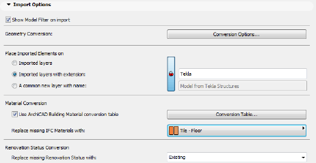
If this option is active, then - after you issue an import command - the Model Filter window will open.
See Model Filter.
This gives you the chance to overwrite, for the purposes of the current import process, the “Import/Export Filter Options” settings of the translator you are using, to fine-tune the elements to be imported (e.g. import only certain element types, or just the elements from a certain story).
See Import/Export Filter Options.
Use Conversion Options to define the geometry creation method (and concurrently the type of the ArchiCAD element being created) for the following IFC element types:
-IFC Site: option to import the geometry of the IfcSite, or not (Without geometry option). If you opt to import the geometry, then you can further decide whether the created element should be an editable Morph or Object.
-IFC elements with complex geometry: when importing IFC Entity elements that cannot be modeled using ArchiCAD building elements (e.g. Column, Beam, Wall) due to their non-extruded (BREP) nature, you can choose to interpret them as either editable Morph elements, with an Element Classification that corresponds to the type of the imported element; or as an Object, with a Subtype that corresponds to the type of the imported element.
-IFC Distribution Elements (HVAC): as above; make the choice for imported HVAC domain element types (IfcDistrubutionElement).
-Unnamed complex IFC profiles: if the imported IFC model contains complex profile attributes without a name (which is possible in the IFC 2x3 scheme), then you have two options: generate new Profile Attributes as part of the import process; or (the default choice) the element will be imported with a “Custom” profile which is not stored as an attribute. (This way, you can avoid automatically generating new attributes.)
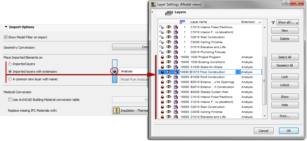
•Place Imported Elements on...
Define the method for placing the imported elements onto ArchiCAD layers.
-“Imported layers” means that ArchiCAD will create new layers that correspond to the IFC layer (IfcPresentationLayerAssignment) names, and will place the imported elements onto these layers.
Note: If layers of the same name already exist in ArchiCAD, no new layers are created; the imported elements are placed onto the corresponding, existing ArchiCAD layers.
•Imported layers with extension
This will create new ArchiCAD layers corresponding to the IFC layers of the imported file, but will add a custom extension (such as “Structural Model”) to each of these layer names. The advantage is that, following the file import, you will be able to sort the layers by extension in ArchiCAD’s Layer Settings dialog box.
This means that the imported elements will be placed onto a newly created, single layer that you define (such as “IFC import” layer). In this case, the import will delete the original layer names of the IFC model.
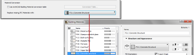
It is possible to map the imported IFC materials to a corresponding Building Material in ArchiCAD. This is recommended if the ArchiCAD file template or the running project does not contain fill types of the same name as those of the imported materials.
1.If the “Use ArchiCAD Building Material conversion table” option is not checked, then ArchiCAD will determine whether the imported IFC material names exist among the ArchiCAD project’s or template’s Cut Fills. If they do, then each imported material will be displayed using the corresponding Cut Fill. If such fills do not exist, then a single Cut Fill type set (at “Replace missing IFC Materials with” option) will be used to display all such imported materials, while preserving the original IFC material names.
2.If the “Use ArchiCAD Building Material conversion table” option is checked, then the missing IFC materials will be displayed using the definitions in the Conversion Table (click “Conversion Table” to bring up this dialog). Here, map the Building Materials available in your project to the names of the imported IFC materials. For example, you might use ArchiCAD’s “Concrete Structural” Building Material to represent all concrete materials entitled “C20” that are imported from a structural program. As a result, ArchiCAD will create a new fill type: it is named “C20”, but it uses the existing fill pattern of the “Concrete Structural” Building Material (provided, of course, that the ArchiCAD project does not yet contain a fill type entitled “C20”).
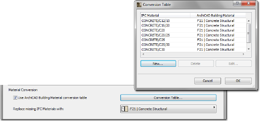
If you have not mapped a particular imported material in this Conversion Table, then that material will automatically be displayed using the fill type defined at “Replace missing IFC Materials with.”
Hints:
•Some of the default translators include predefined Conversion Tables, whose settings you are free to expand or edit in the translator’s duplicated copy (provided that the translator is not locked).
•You cannot import or export these Conversion Tables as separate .xml files; you must import/export them together with entire translator file itself (use Browse to import).
“Replace missing renovation status with:” Choose a Renovation status in ArchiCAD for imported elements that do not have an assigned renovation status.
For export, the following options are editable (provided that the translator is not locked).
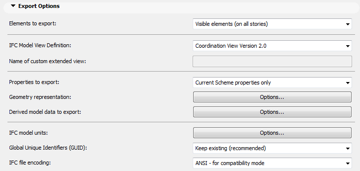
•Elements to export
Use the element filter for export to configure the current translator.
See Step 3 at Export Functions.
This value determines the default filter used by the export process, but you can still change the filter in the export dialog.
Note: If there are selected elements in the project when you start the export, this control automatically changes to “Selected elements only”, regardless of the translator’s default setting.
•IFC Model View Definition
Choose whether you want to save the IFC model according to a version of the widely used so-called “Coordination view” standard, or another Model View Definition (MVD). If the predefined list does not contain the desired Model View Definition, choose “Custom”, and enter the header info required by the MVD in the “Name of custom extended view” field.
Note: Depending on the MVD you choose, some of the following “Geometry representation” and “Derived model data to export” will not be modifiable. For example, if you are using “Coordination View (Surface Geometry)”, the geometry representation of every element is required to be BREP. Another example: the “Concept Design BIM 2010” MVD requires the export of IFC Type Product element geometries, while the “Coordination View” does not allow this.
Use this option to define which property set (IFC Property and Classification Reference) to use when saving the model: either all properties available in the IFC Manager, or just the current properties in the IFC Scheme Setup (seen with the “Show only Scheme items” display mode in IFC Manager). Thus, for example, if only the COBie.xml scheme is active in the IFC Scheme Setup dialog box, then if you choose “Current Scheme properties only”, only data defined as part of the COBie scheme will be saved.
•Geometry representation
•Use BREP geometry for all elements: If you would like to export all model elements with BREP (boundary representation) geometry only, activate this option. This option also sets BREP geometry representation for all complex elements, elements in Solid Element Operations, elements in junctions, etc. (see later). The built-in “Coordination View (Surface Geometry)” Model View Definition exporter always uses and requires this geometry export type option.
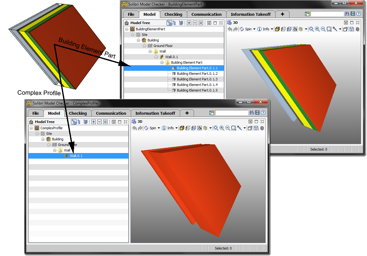
•Explode Composite and Complex Profile elements into parts: This will save composite elements (e.g. Slab or Wall) and Complex Profiles (e.g. Column, Wall, Beam) as so-called “Building Element Parts”. This means that the main element (e.g. IfcWall) will be saved as a container element without geometry, and its parts (the skins or profile components) will provide the geometry. Use this option to ensure the correct export of the individual colors assigned to the Building Materials of each component. This export option retains the original colors of all building parts, instead of exporting them in all one color.
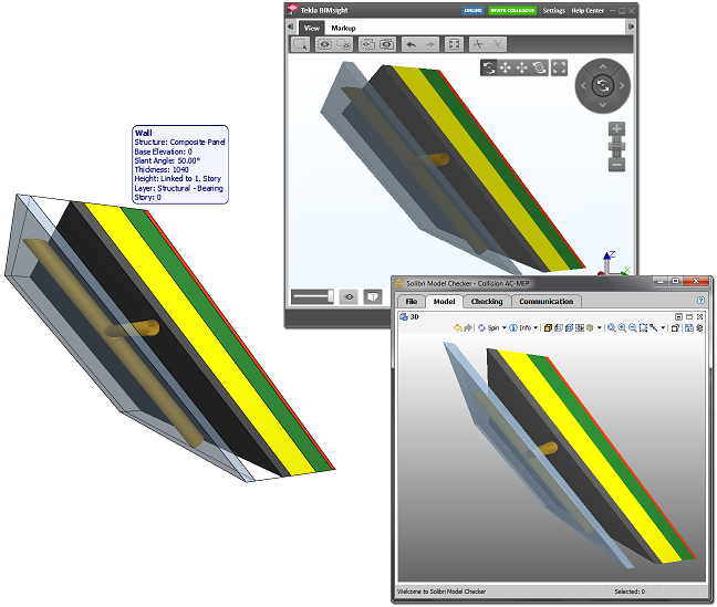
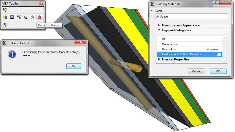
•Export geometries that “Participates in Collision Detection” only: For each Building Material, you can define whether it should participate in participate in collision detection or not (Options > Element Attributes > Building Materials > Tags and Categories). With this export option, you can export composite elements/complex profiles that don’t have solid geometries as real air gaps. This way, for example, MEP engineers (who receive the ArchiCAD IFC file) can place pipes in the gaps without collision detection, and only those element parts having real geometry will participate in Collision Detection in model-checkers and in GRAPHISOFT MEP Modeler.
• Multi-skin complex geometries: This option will affect multi-skin (Composite or Complex Profile) ArchiCAD elements having complex (e.g. slanted) geometry representation.
-Building element parts: An element (e.g. Wall) is logically made into an IFC element (e.g. IfcWall) that includes building element parts. The advantage of this option is that each building element is assigned the IFC material or profile that is represented by its Building Material (Cut Fill) in ArchiCAD.
-Complex profiles: An element is logically made into an IFC element, to which a profile geometry or material list will be assigned, in the form of an IFC material. (The receiving application will not know the precise order of the different components/skins.)
Note: This option is affected by the “Partial Structure Display” (Document menu) currently in effect, if the view’s visible elements are being exported. For example, if the “Core Only” Partial Structure Display is in effect, then the “Complex profiles” option will have no effect on a slanted composite wall that has a single core, because in this case the wall will not count as a composite element.
•Elements in Solid Element Operations
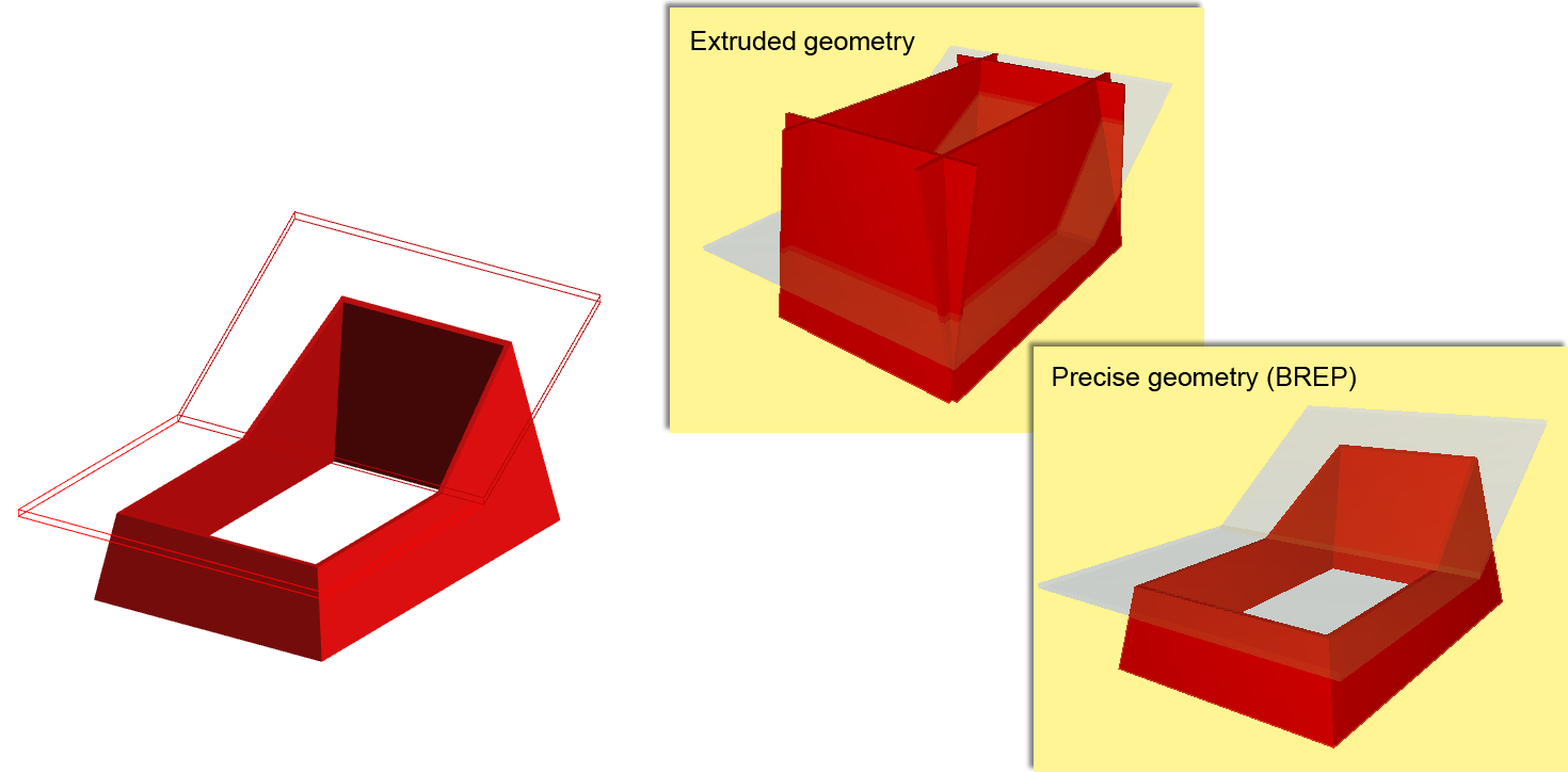
-With the extruded/revolved geometry method, elements edited with Solid Element Operations will be exported according to their definition geometry - for example, without any automatically added intersections. With the BREP method, they will be exported as they are displayed in ArchiCAD because of Solid Element Operations.
-Extruded/revolved: This is the standard IFC geometry representation, which retains the elements’ parameter values (such as thickness, height, location of reference line or edge, skin structure of composite materials) - however, certain specialized sections are not retained. This is the format usually supported by static analysis programs, because while it is important to retain and possibly to modify the elements’ parameters, their special cut angles (such as the slanted edge of a slab) are not important.
-BREP: This method comes closest to reproducing the shape of the element, together with its specialized sections and connections. However, the element’s parameters are lost, and BREP (Boundary Representation) elements from an imported IFC file are transformed into non-editable elements. Since this method provides the most exact reproduction of element geometry, it is useful in the “reference model” workflow.
-Choose whether to export the elements as either extruded/revolved geometry or with BREP.
-If you prefer the extruded/revolved geometry, you can export the elements without junctions - that is, without the priority-based intersections. In this case, the export process is faster. This option is recommended for structural analysis programs, for which the elements’ reference lines/surface information is sufficient, and detailed intersections are not required.
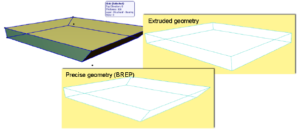
The difference between BREP and extruded/revolved geometry representations is illustrated here:
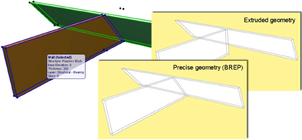
•Slabs with slanted edge(s): With the extruded method, slabs will be exported with vertical edges, even though their original geometry included a slanted edge. With the BREP method, such slabs will be exported using their correct original geometric representation.
•Use legacy geometric methods as in Coordination View 1.0: Use this option if you have created your own, custom MVD that is based on the geometry methods of Coordination View version 1.0.
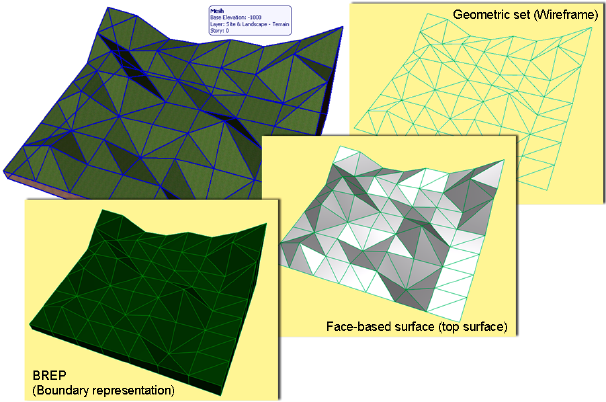
•IFC Site geometry: In ArchiCAD, the IfcSite geometry can be created with Mesh elements, with Objects with subtype “Ifc2x_Site” and any modeling element (e.g. Slab, Morph) classified (Element Classification) as “Site Geometry”. Depending on whether these elements are visible/selected in the view from which you begin the export, and depending on your choices at “Export” options, these elements will be exported. Use the drop-down list to apply a geometric representation to these elements in the IFC model.
Make your choice depending on which kind of site geometry your partner’s application is able to read:
-Boundary representation (BREP): Geometric representation as solid bodies enclosed by their superficies and boundary surfaces. BREP is a simple form of boundary representation model in which all faces are planar and all edges are straight lines.
-Face-based surface (top surface): Geometric representation of the superficies (top surface) only.
-Geometric set (wireframe): Geometric representation with contours and points.
Note: ArchiCAD is able to import all three kinds of IFC site geometry representations.
The following options enable you to export additional data in addition to the elements, which can be useful for data exchange with energy analysis or cost estimation programs:
•Space containment: Space containment defines the relationship between ArchiCAD Zones (IfcSpaces) and Furnishing, Mechanical (HVAC) and other contained elements defined by Object and Morph tools within the space. Check this box if you would like to send the model to a facility management application.
-Note: Object and Morph elements will be in space containment only if the center of these elements’ bounding box falls within the ArchiCAD Zone.
-Hint: Space containment content can be verified in IFC Manager, by viewing the contents of the containment tree in “Space Containment” mode. (See IFC Options.)
•Bounding box: Check this box if you would like to export the dimensions of the building elements’ bounding box.
•Geometry of Type Products: Use this to save the geometry of the various IFC Type Product elements. Each type (e.g. IfcWindowStyle) will use a representative geometry of the elements that belong to it (e.g. IfcWindows).
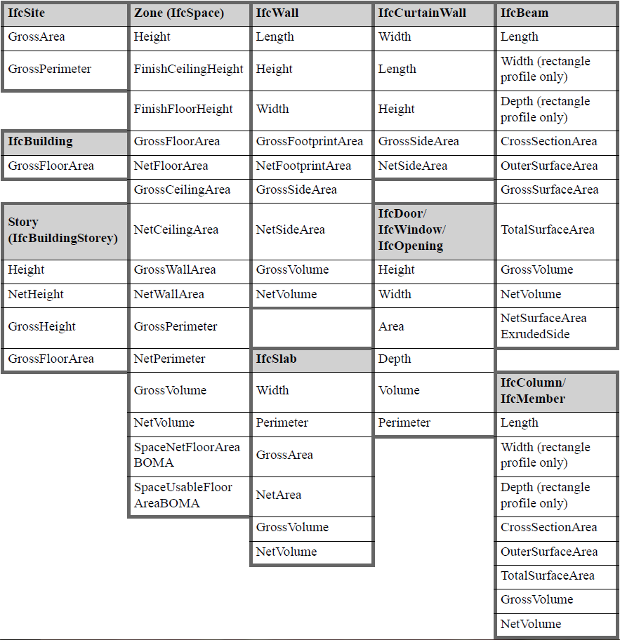
•IFC base quantities (size, area and volume): Check this box to add Quantity Takeoff parameters to Wall (IfcWall), Column (IfcColumn), Beam (IfcBeam), Slab (IfcSlab, predefined type Floor), Roof (IfcSlab, predefined type Roof) and Zone (IfcSlab) elements to the IFC model. This data is useful in the Interoperability with cost estimation applications.
For example, the following quantities (IfcElementQuantity) can be exported together with IfcWall element: Length; Height; Gross Volume; Net Volume (volume reduced e.g. by columns embedded into the wall); Gross Footprint Area (doors are not considered); Net Footprint Area (area reduced by door footings); Gross Side Area (openings are not considered); Net Side Area (area reduced by openings).
The following table summarizes the base quantities by entity types automatically calculated and exported when using this derived data export option. The values of IfcSite’s base quantities can be set manually at Info > Project Info (Site Gross Perimeter and Site Gross Area).
•All ArchiCAD BIM parameters: This option adds all ArchiCAD parameters (including Library Part parameters) and quantities (available in Schedules) to the exported IFC file as IFC Properties grouped in property sets having the prefix “AC_Pset” (for example in case of a Library Part: "AC_Pset_"Library Part name"). This option can be useful when exchanging data with programs that can read such data. For example, quantity takeoffs can read quantities; a model viewer or FM program can read properties.
-Note: Choosing this option will significantly increase the IFC file size. Thus, use it only if you know that the target application can read these data.
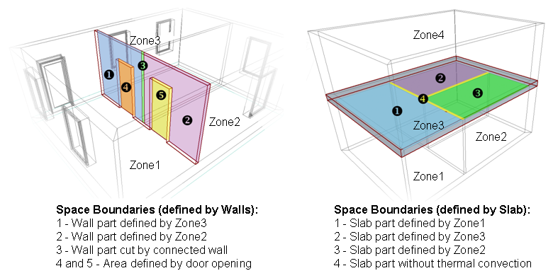
•IFC Space boundaries: ArchiCAD Zones include precise geometry data that are useful to thermal calculation software applications. Zones are 3D solids in geometrical aspect and in normal cases are bordered by two slabs and four walls. Space boundaries define the logical connection between ArchiCAD Zones (IfcSpace) and the building elements that enclose them. In practice, Walls, Slabs, Roofs, Windows, Doors etc. all have different thermal conductivity properties. If you activate the “IFC Space boundaries” option, ArchiCAD will export Space boundaries and their relations (IfcRelSpaceBoundary) together with the Zones (IfcSpace) to the IFC file. In other words, ArchiCAD will calculate the position, size and adjacency of the elements that border each Zone. ArchiCAD divides the Zone boundaries according to the areas defined and cut by connected elements and openings.
•ArchiCAD Zone Categories as IFC Space classification data: Check this box to export the Zone Categories data (Code and Name) of ArchiCAD Zones as their (IfcSpace) IFC Classification Reference data (ItemReference and Name).
Set the unit type globally for the export of all geometric properties (length, angle, area and volume), all time properties (and Time Series Schedule data), and all currency-required properties. Choose metric or imperial units for the geometric properties.
Note: When doing an import, the imported elements and data are always displayed using ArchiCAD’s model unit preference (Options > Project Preferences).
•IFC Global Unique Identifier attribute (GlobalId)
The “Keep ArchiCAD IFC ID” option means that IFC GlobalId Attributes of elements assigned automatically by ArchiCAD will be kept in the exported IFC model. The “Keep ArchiCAD IFC ID” option is useful when using other programs to compare two IFC model versions arriving from ArchiCAD. The alternative option is “Generate new”. Each new exported IFC file will generate brand new GlobalIds for the elements, so that each new exported version is entirely separate from the previous versions.
Note: The IFC Global Unique Identifier attribute (GlobalId) settings option has no effect on the Merge to IFC Model export process.
See Export Functions.
Use this option to define the character coding used by the .ifc or .ifcZIP file.
See File Types.
-ANSI: This is the default option for compatibility reasons, since earlier ArchiCAD versions and many other applications (e.g. structural, MEP) use only ANSI.
-Unicode: The recommended option if you are exchanging an IFC model with a receiving application using a different platform (e.g. ArchiCAD on MacOS vs. Windows) or a different language environment (such as a different language version of ArchiCAD).
Note:
-Switch to the Unicode option only if you are certain that your data exchange partner’s application supports it.
-The Unicode option has no effect when saving to .ifcxml format, because exporting to that format always uses UTF 8 coding.