
For a description of generic settings common to all tools in the Toolbox, see Working in Tool Settings Dialog Boxes.
The Object tool is used to place object type library parts into the project.
The panels of the Object Settings dialog box is similar to those of other Library Part elements.
See Settings of Library Part Elements.
Browse Folders and Subfolders
In Object Tool settings, you can access a wide variety of objects that are not part of a dedicated subtype. These objects are divided into three main folders: Basic Library; Visualization Objects; and Add-On Library, and several sub-folders. As you can see by the folder names, the Basic Library contains all kinds of Furnishings (Beds; Chairs; Office Equipment, etc.); Decorations (such as clocks and vases); Health/Recreation items (such as a piano, a billiard table, a TV). Additional folders contain Building Structures (such as fences and moldings); Special Constructions (such as fireplaces and shutters); Mechanical Elements (such as air conditioners and elevators); and 2D Elements (such as electric and graphic symbols.)
The Visualization folder contains Site improvements (e.g. trees) and objects depicting People and Vehicles.
For information on searching for library parts, see Search for Library Part.
Settings Panels
The Object Settings dialog box contains the following panels:
•Preview and Positioning
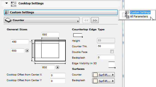
•Custom Settings (the name of this panel varies, and is only active if the chosen library part contains a user interface script. If it does not, the panel is grey.)
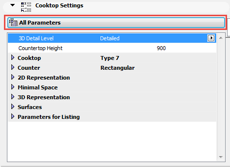
•All Parameters: Some objects have Parameter lists as an alternative interface for the graphical Custom Settings. If you prefer the Parameter list, choose this from the Custom Settings Panel pop-up:
•Floor Plan and Section
•Model
•Listing and Labeling
•Tags and Categories
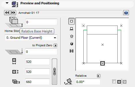
Object Preview and Positioning Panel
Use the fields to enter the following values for the Object:
Relative Base Height: Enter a value to define the object’s base elevation relative to its Home Story.
Bottom Elevation [to Reference level]: Enter a value to define the object’s absolute base elevation, measured to Project Zero or to any other custom-defined Reference Level.
See also Reference Levels.
Note: The Bottom Elevation shows the current elevation of the Object bottom. Thus, this value serves as a calculation tool only, not a link. If you change the position of a Reference level, the Object will not change its position.
Dimensions 1 and 2: enter the two orthogonal size values (e.g. length and width) of the object.
Click the chain icon to keep these values proportionally constant.
Height: Enter the object’s height.
Enter a rotation angle for the object, if any. Click the black arrow and choose either
• Relative to Orientation (the angle will be measured relative to the Oriented View);
See also Oriented View.
or
• Absolute to Coordinate System (the angle will be measured from the (0,0) point of the project coordinates).
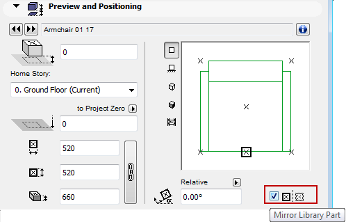
Check the Mirror Library Part box to mirror the chosen Library Part when placing it, or to mirror a selected object. (View the preview after checking this box to see how the object will be placed.)
Information
Click the information icon to view a brief description of the object.
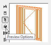
Preview Options
The Preview Area at the right shows you the object in different displays, depending on which of the five icons (at left) that you choose. As you set different parameters for the object, keep an eye on this preview to see the effects of your edits.
Click among the Preview Options to vary the preview picture:
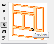
Move the cursor inside the Preview Area and the cursor will change to a “flip” arrow, allowing you (in the 2D Symbol or 3D views) to alternately view each side of your Library Part.
The preview options, from top to bottom:
•2D symbol
•hidden line front view
•hidden line axonometry
•3D shaded axonometry
•predefined preview picture
Note: To modify the predefined preview picture, use the Preview Picture controls in the GDL Object Editor.
See Preview Picture.
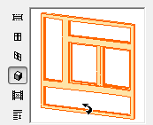
Move the cursor inside the Preview Area and the cursor will change to a “rotate” arrow, allowing you (with successive clicks) to rotate the 2D Symbol or 3D View of your Library Part.
Placement Anchor
Objects can be positioned by their hotspots, defined in the 2D symbol of the Library Part. One Hotspot is initially defined as the primary hotspot. This hotspot is marked with a highlighted rectangle, and it will act as the default insertion point and anchor point for the Object.
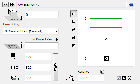
The other hotspots are displayed as X’s. Click any of them if you wish to use it as an insertion/anchor point instead of the default primary hotspot.
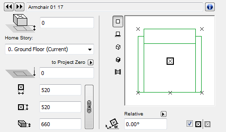
Home Story: Choose a Home Story for the Object: by default, it is the Current Story, but you can click Select Story instead and choose any other Story as the Home Story.
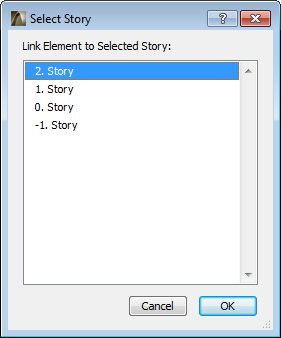
For more information, see Home Story.
This panel lets you set parameters defined for the Library Part.
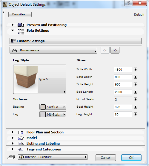
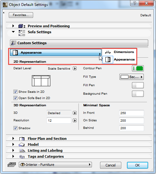
The available parameters vary depending on the object. Click the pop-up menu to access different parameter categories.
For information on transferring modified parameters from one object to another, see Parameter Transfer Between Objects.
The Minimal Space parameter (included with many Objects from the default ArchiCAD Library) defines the area surrounding the placed object that you want to keep free. You can opt to display the minimal space of all objects in 2D views, depending on the global options set at Model View Options.
See Miscellaneous Model View Options for Library Parts.
Object Floor Plan and Section Panel
Use this panel (or the equivalent controls in the Info Box) to define the display of the Object in Floor Plan and Section views.
Show on Stories: Use this pop-up (where available) to control the stories on which objects will be displayed: on its Home Story only, or in outline form on other stories as well.
Uniquely among ArchiCAD elements, the Object/Lamp can be set to be shown One Story Up or One Story Down only.
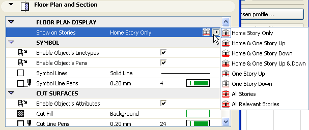
For more information, see Show On Stories.
These checkboxes in the Floor Plan Display Panel allow you display the object using the relevant parameters (Linetypes, pens, fills) which have already been defined for the object, and which are listed in object’s Parameter list
See Object Custom Settings Panel, above.
If no such parameter is defined (for example, if no line type is listed in the object’s parameter list), then checking the box will have no effect; the object will be displayed using the attributes defined in the Floor Plan and Section panel.
The Custom Settings and Listing and Labeling panels of Objects/Lamps and Stairs are similar to those presented for the Window and Door type elements.
Note: Custom Settings are available only for GDL objects having a user interface script.
For more information, see Door/Window Tool Settings and Listing and Labeling Panels.
Use this panel to if you want to define one single Surface for the Object. To do this, you must disable the Use Object’s Surfaces checkbox.
Use the pop-up to select a Surface for the Object.
Checking the Use Object’s Surfaces checkbox will ignore the surface in the Model Panel, and will apply the surface that was used when creating the Object.
Object/Lamp is cropped by one or more roofs: If this message is activated, it indicates that the currently selected Object (already placed in the project) was cropped by a roof using Crop to Single-plane Roof.
•In this case, the Undo All Crops button is also activated. Click to restore the original geometry of the selected object.
For more information, see Crop Elements to Single-plane Roof.
Custom Texture defined in the 3D window: If this message is activated, it means that the currently selected object (already placed in the project) has been assigned a custom 3D texture.
•In this case, the Reset Texture button is also activated. Click to restore the origin of the Texture of the selected object.
For more information, see Align 3D Texture.
Object/Lamp Listing and Labeling Panel
See Listing and Labeling Panels.
Object/Lamp Tags and Categories Panel