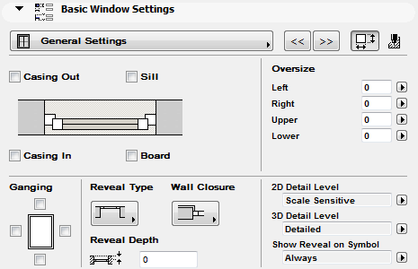
The following is a description of the General Settings page of the Graphical Interface Panel of Window Settings, for a window in the INT ArchiCAD Library.
Casing
Use the Casing Out and Casing In checkboxes to add Casing to the outer and/or inner side of the window.
•Casing options can be defined in the Casing Settings tab page of the Graphical Interface panel.
•If you add a Casing, the Turn Plaster options for the side of the window that has a casing will not be available.
See Turn Plaster.
Sill, Board
Use the Sill and Board checkboxes to add a Sill and/or a Board to the window.
•Sill and Board options can be defined in the Sill Settings and Board Settings tab pages of the Graphical Interface panel.
Note: If you turn on Ganging for the bottom of the window, the Sill/Board options will be grayed.
See also Ganging.
Ganging
You can align windows horizontally and vertically with these parameters.
You must check these boxes both for this window and for the adjacent one so that the window symbol is displayed correctly.
As a result of ganging, the connecting lines between the windows’ casing, sill, board etc. disappear - as if they were a single unit
Note: In the USA library, ganged windows are separated by a mullion.
If you use ganging, some other structure options for this window may no longer be applicable and will be grayed or eliminated.
Reveal Type and Depth
From the pop-up list, choose a Reveal Type to use for this window, or choose one of the No Reveal options. Enter a value for the Reveal Depth.
•You can also choose a Reveal Type and set Reveal Depth on the Reveal Settings tab page of the Graphical Interface Panel.
•Reveal Depth is also set on the Preview and Positioning Panel.
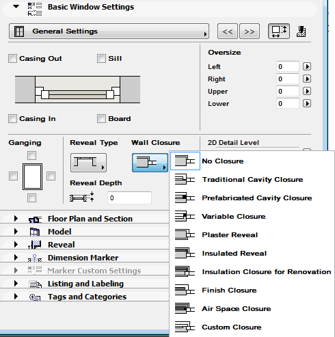
Wall Closure
This control is applicable if you have placed the window in a composite wall.
Choose a predefined or custom Closure from the pop-up list. Available closure types vary depending on the type of reveal used for the window.
•Closure options can be defined in the Wall Closure tab page of the Graphical Interface panel.
See Wall Closure.
Oversize
Enter values if you want to increase the wall hole cut by the window, on its left, right, upper and/or lower sides.
Note: Entering an Oversize does not (unlike the Tolerance value) affect the Nominal Size of the window.
2D and 3D Detail Level; Reveal Display
Choose options for the level of detail with which to display the window in both 2D and 3D.
For the 2D symbol, if you choose Scale Sensitive, then the amount of detail shown varies depending on project scale. Otherwise, you can fix the detail level to a given level (e.g. 1:200).
For the 3D Symbol, choose either Detailed, Simple or Off.
•Off: The window is not displayed at all and is shown as an empty opening.
Show Reveal on Symbol: Choose the scale at which the reveal should be displayed in 2D views. (Reveal will not be displayed if the scale is larger than the chosen value.)
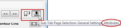
General Settings - Attributes
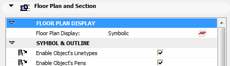
To set general fill, material and pen attributes for the window, click the button (at the top right of the General page) to access the Attributes controls.
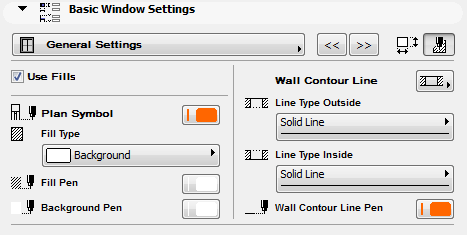
Attributes you set on this page will only affect the window if its Floor Plan Display control is set to Symbolic, and if the Enable Object’s Linetypes/Pens boxes are checked.
•On the General Settings page (Attributes sub-page), check the Use Fills box to enable all fill parameters on every Attributes sub-page. If Use Fills is off, the opening display will not use any fills on any of its components. (The Fill controls will be grayed on all of the Attributes sub-pages.)