Open the Profile Manager from:
•Options > Complex Profiles > Profile Manager
•Options > Element Attributes > Profile Manager
Use Profile Manager to edit or create Complex Profiles in the Profile Editor window, or to choose and manage profile elements in the model.
For the workflow, see Create or Edit Complex Profile.
This section describes the controls of Profile Manager.
Create New/Duplicate/Rename/Delete Profiles
These icons are in the Manage Profiles panel of Profile Manager.
![]()
See also Delete and Replace Attributes in a Model.
“Use With” - Define Profile Element Types
In Profile Manager, the Use with buttons, like those in other Attribute Settings dialog boxes, determine which ARCHICAD tools can be used to place the current profile.
Click Edit, then click on the Use With tool icons:
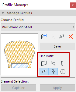
Note: Profile “Use With” definition is also available in Attribute Manager: See Profiles (Attribute Manager).
Use this panel to show or hide elements in the Profile Editor window.
This panel is active only if the Profile Editor is open.
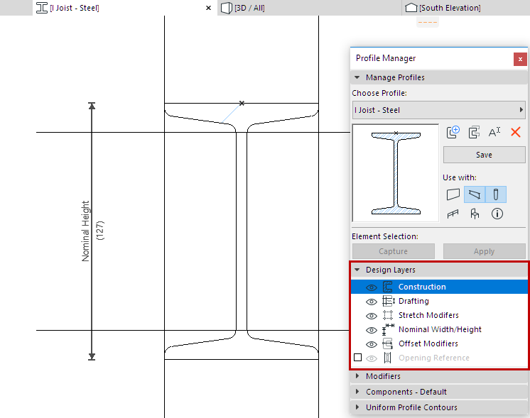
Show/hide Fill or Hotspot elements in the Profile Editor window. These will be saved and used as part of the profile.
Show/hide elements drawn with any other drafting tool (e.g. Lines, Arcs, Polylines).
These will be saved as part of the profile attribute, but they will not be visible in the placed profile.
Stretch Modifiers
Show/hide Stretch Modifiers in Profile Editor window.
See Stretch Modifiers.
Show/hide the dimensions indicating the profile’s Nominal Width and Height, in the Profile Editor window.
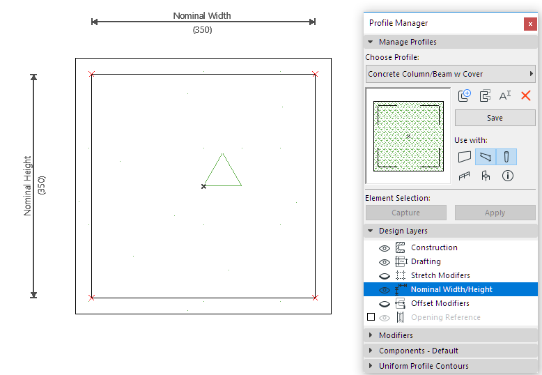
The Nominal Width/Height - a listable element parameter - will be displayed in the placed element’s Settings dialog. The values are editable if Width and/or Height Stretches are enabled in the Modifiers panel.
See Nominal Width/Height.
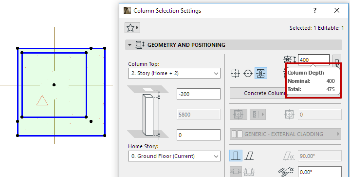
In contrast, the Total Width/Height also includes element-level adjustments via Offset Modifiers, and reflects the overall bounding box size of the element. The Total Size is not editable in the element’s Settings dialog, due to the constraints of Offset Modifiers.
Nominal Width and Height dimensions can be repositioned by clicking and dragging on their dimension lines. Their lengths can be modified and aligned to another part of the profile - including outside of the Profile bounding box, by clicking on the ends of the nominal dimensions. If the lengths are not modified, their lengths will automatically resize to follow the bounding box of the Fills as defined in the Profile Editor.
Nominal Dimension ends, like Offset Modifiers, can be associated to Fill nodes, but this may cause an over-constraint. In this case, a warning will appear.
Offset Modifiers
Show/hide the dimensions and assigned edge/node highlights of Offset Modifiers.
Even if this is set to “hide”, an Offset Modifier currently selected in the Modifiers list will always be shown.
See Offset Modifiers.
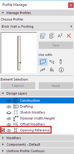
•Check this box to display lines representing the reference line at which doors/windows will be placed, once you place the profile wall on the plan.
•Click the eye icon to show/hide the Opening Reference lines in the Profile Editor window.
•If necessary, edit, extend or break the lines to conform to the shape of the profile, so that openings will be placed and oriented in the correct location.
If you do not switch on Opening Reference, doors/windows will be placed along the profile element’s bounding box.
Modifiers Panel
See:
Select a Fill component in the Profile Editor window.

Use the Components Panel of Profile Manager to edit the following parameters:
Component Type
Define the selected component as either Core, Finish or Other. This definition will affect the Partial Structure Display of the complex element.
See details at Partial Structure Display.
Override Surfaces
Check Override Surfaces to choose a new surface from the pop-up. Otherwise, the selected component will use the surface defined in the Fill’s Building Material.
If you override an individual Fill edge with a custom surface in Profile Editor, this will be reflected as “Various” in this panel.
Show Cut End Lines
Check this to display Cut End Lines.
Define Line Type and pen of the selected Profile Fill component. This line type and pen are used for end lines when the element is cut.
List Component Area by
Choose either Base Line or Base Circle to define how ARCHICAD should calculate surface area for this component, in an Interactive Schedule of Components.
To view and edit the Base Line or Base Circle in Profile Editor, make sure you have turned on View > On-Screen View Options > Component Area Base Line/Circle.
For more information, see Component Listing Parameters in the Interactive Schedule.
Apply uniform line types and pen colors to cut lines and to all separator lines at once. (This panel is active only if the Profile Editor window is open.)
These settings will be applied to the placed profile, and reflect any changes made by Offset Modifiers.
Click Save, then view the feedback in the Preview window of Profile Manager.
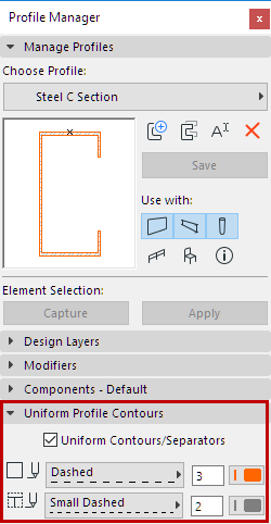
Contours: Choose a uniform line type and pen color for all contour lines (outer lines) of the profile element.
Separators: Choose a uniform line type and pen color for all of the separator cut lines (inner lines) of the profile element.
Notes:
–Lines that separate two fills having the same Building Material will not be eliminated.
–Edges customized to Off (Show Cut Line is Off; see below) will not apply uniform contour settings.