For a description of generic settings common to all tools in the Toolbox, see Working in Tool Settings Dialog Boxes.
For general information, see Walls.
Wall Geometry and Positioning Panel

By default:
•Wall top is linked to one story up
•Home Story is the current story.
The story to which the Wall bottom is linked is called the Home Story, but you can offset the bottom in either direction.
Use the controls in this panel to change any of these values, and to define the geometry and complexity of the Wall element.
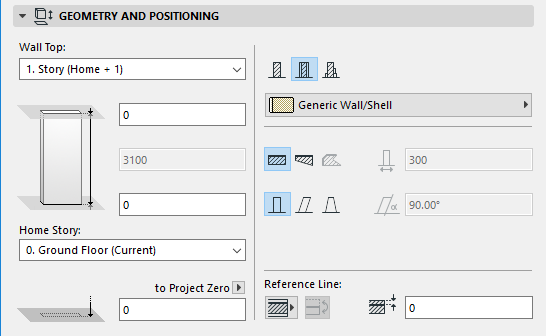
Wall top: Use this control to either top link the Wall relative to its Home Story (Home+1, Home+2, etc.), or to make it a fixed-height wall (choose “Not linked”).
If you later modify the positions and heights of stories in your projects, the heights of any linked Walls will follow automatically.
•Optionally, define an offset for the Wall top from its top linked story (the Wall height changes accordingly). This offset value can be positive, negative or zero.
The offset field is not available if the Wall has no top link.
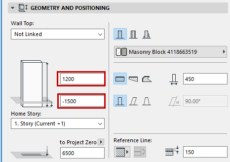
Wall height: Enter a value for the total height of the Wall. (For a top linked Wall, this field is not editable.)
•The Wall height value is affected by the top and bottom offsets, if any.
Home Story
See Home Story.
Bottom Elevation [to Reference Level]
Calculates the current elevation of the Wall’s reference line, as measured from the Reference level (by default, this Reference level is Project Zero).
Click the pop-up arrow to change the Reference level, if needed.
Notes:
–Reference levels are defined at Options > Project Preferences > Reference Levels.
–This is a calculated value, not a link. If you change the Reference level, the bottom of the Wall will not change its position.
Click one of these icons to define the Wall as Basic, Composite, or Complex Profile, and then choose an attribute that reflects its structural properties:
•For a Basic Wall: use the pop-up to choose its Building Material.

•For a Composite Wall: use the pop-up to choose its Composite structure.
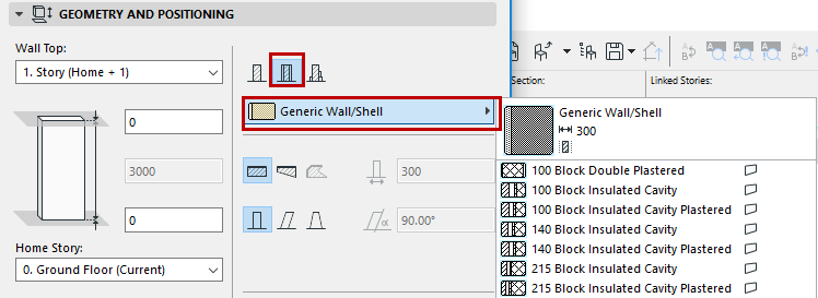
Note: This pop-up shows only those Composite Structures whose “Use With” control includes Walls. Composites are defined at Options > Element Attributes > Composites.
•For a Complex Profile Wall: use the pop-up to choose its Profile.
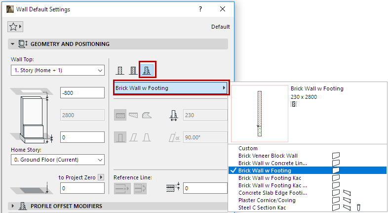
Note: This pop-up shows only those Profiles whose “Use With” control includes Walls. Profiles are defined at Options > Element Attributes > Profile Manager.
Geometry Method
Click one of these three icons to draw the Wall as either straight, trapezoidal or polygonal.
•These options are not available for Complex Profiles.
•The polygonal option is not available for composite Walls.
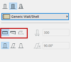
Enter a value for the wall thickness.
•If you are creating a trapezoidal Wall, two thickness fields are active: enter a thickness value for each end of the Wall.
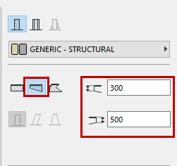
•The thickness of a composite Wall is the total value of the individual skins as set in Options > Element Attributes > Composites. If you are creating a composite Wall, the thickness field is consequently not editable here.
•Thickness does not apply to polygonal Walls; the field cannot be edited.
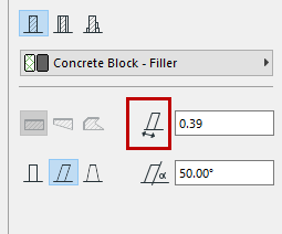
•The thickness of a slanted Wall is its thickness perpendicular to its slant vector:
•The thickness of a double-slanted Wall equals the width of the Wall base.
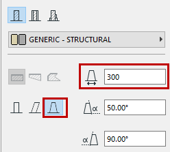
The Wall Complexity icons give you a choice of Wall geometry: Straight, Slanted, or Double-Slanted. (Wall Complexity controls are not applicable and not available for Trapezoid Walls and Polygonal Walls.)
•For a slanted or double-slanted Wall, enter the value for the slant(s) in degrees.
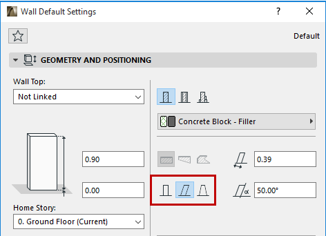
For more information, see Create a Slanted or Double-Slanted Wall.
This checkbox is only visible when the chosen geometry method is Polygonal Wall. It controls the display of wall contours when connecting such a wall to other, plain walls.
For more information, see Create a Polygon Wall (PolyWall).
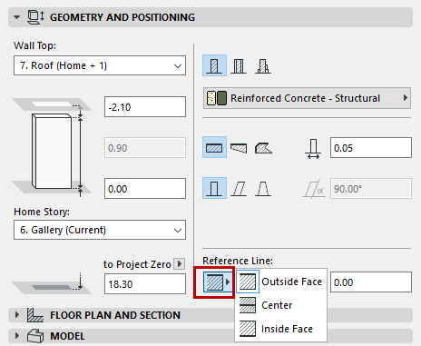
Click an option to define the Wall’s reference line.
Note: Reference line controls in Wall Settings do not apply to Polygon walls. (Polygon wall reference lines can be moved graphically via the pet palette.)
A basic Wall has three possible reference lines: Outside Face, Center, or Inside Face.
By default, the reference line runs along the outside face.
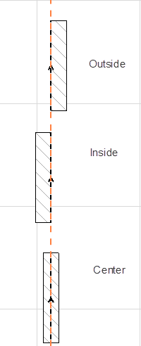
A composite Wall has six possible reference lines: Outside/Center/Inside of the Wall, plus Outside/Center/Inside of the Wall core.
Note: If the chosen composite structure has no core, then the core-related Reference Line choices are grayed out.
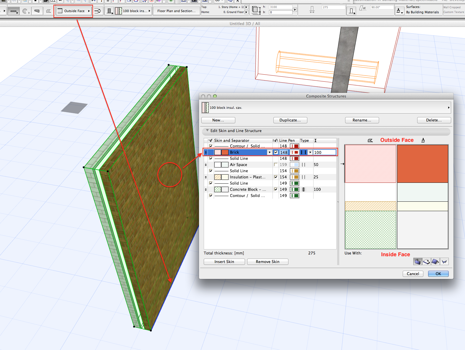
By default, the reference line runs along the outside face.
For a composite, the “outside” face is the top skin of the composite, in Composite Settings.
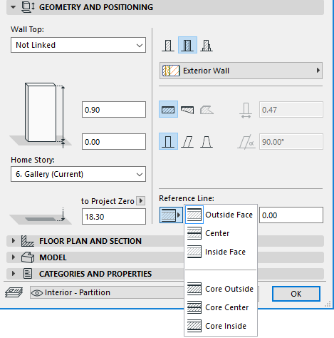
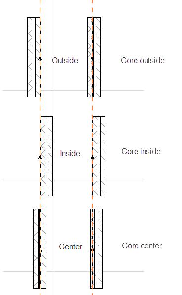
A Trapezoid wall has two possible reference line locations: Outside Face or (if it is a composite Wall that has a core) Core Outside.
Reference Line Offset: If using an “outside” or “inside” reference line, enter a positive offset to move the reference line toward the center (or center of core) of the Wall. A negative offset will move the reference line away from the center (or core center). (No offset is available if the reference line is in the center or core center.)
For more information, see Wall Reference Line.
Wall Floor Plan and Section Panel
See Element Display in Floor Plan and Section
Wall End Lines: This pop-up gives you four ways to display a freestanding wall on the Floor Plan. The options let you show or hide one or both end lines of the wall. (The end line is the contour line perpendicular to the longitudinal axis of the wall.)
This panel affects the 3D display of the wall.
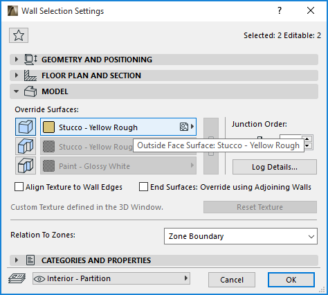
Override Surfaces: Click the toggle button of any or all three pop-ups if you wish to override the surface assigned to this element (in its Building Material). You can override the surfaces of the Wall’s faces (outside and inside), and/or all Wall edges.
See also Override Surfaces With Surface Painter.
For information on assigning surfaces to a Polygon wall, see Create a Polygon Wall (PolyWall).
•For a composite Wall, the “outside” surface is the first listed skin of the composite, in Composite Settings.
•For a profile Wall, there are two surface override possibilities: Extrusion edge and Ends surface.
Note: You can also apply a Custom surface to any edge(s) of the profile element.
See Apply Custom Surface or Line to Profile Edge.
Click the chain icon to assign the last surface chosen to all faces and edges. Deselecting the chain icon will restore the surfaces that you originally set for each wall face/edge.
Align Texture to Wall Edges: Check this box to place the texture origin at the bottom corner of the wall. This can be useful, for example, on freestanding walls to avoid a fragmented texture on the edges.
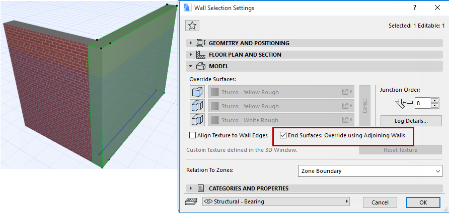
End Surfaces: Override using Adjoining Walls: Check this box if you want the selected Wall’s end surface to take on the surface of the adjoining Wall.
Note: Any adjustments to the surface texture alignment will be correctly reflected on both walls.
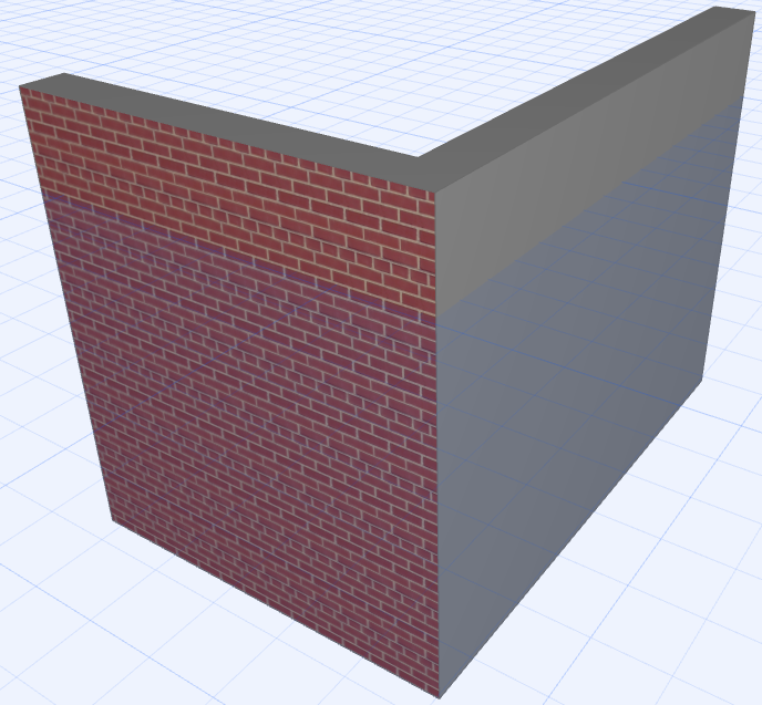
For more information, see Crop Elements to Single-plane Roof.
Custom Texture Alignment: If this message is activated, it indicates that the currently selected wall (already placed in the project) has been assigned a custom 3D texture.
•In this case, the Reset Texture button is also activated. Click to restore the origin of the Texture of the selected wall.
Note: The Custom Texture Alignment text serves as feedback on the condition of the selected wall. If it is greyed out, no custom 3D texture has been assigned yet.
For more information, see Align 3D Texture.
Junction Order is relevant when
•two Walls meet whose Building Materials have the same priority
•3 or more Walls meet in a junction
A higher Junction Order number takes priority over the lower.
When 3 or more Walls meet in a junction, the relative Junction Order of each Wall determines which two Walls are joined first.
The Log Details button opens a dialog box for defining the display of walls constructed from logs:
•Use Log Wall: Check this box to use a Log Wall.
Note: ARCHICAD calculates the number of logs from wall and log heights.
•Start with half log: Check to start the wall with a half-height log.
•Log Shape:
–Square logs
–Rounded on Outside Face
–Rounded on Inside Face: Use logs that are cambered on the inside. The outside wall face will remain flat.
–Rounded on Both Sides.
•Log Radius: choose an option for measuring log radius: either from the log centerpoint, or from the middle point of the opposite log.
•Surface of Horizontal Edges:
–As in Wall Settings: Click this radio button to apply the Building Material’s surface.
–Override with Outside/Inside Face Surface
Relation to Zones
See these topics: