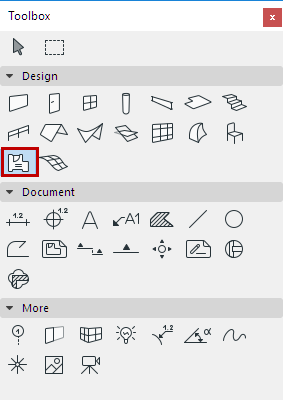
For a description of generic settings common to all tools in the Toolbox, see Working in Tool Settings Dialog Boxes.
Zones are 3D elements, whose floor plan representation consists of zone fills and zone stamps.

For more information, see Zones.
Zone Name and Positioning Panel
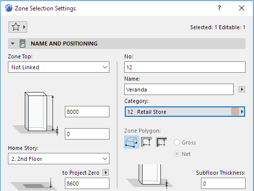
Zone Category: Choose a Zone category defined in Options > Element Attributes > Zone Categories. Their definition includes the Category name, code, color and zone stamp, and a set of parameters.
For a detailed description, see Zone Categories.
Zone Name and Number (No.): Enter name and number values in these fields for each Zone individually.
By default:
•The Zone top is linked to one story up
•The Home Story is the current story.
The story to which the Zone bottom is linked is called the Home Story, but you can offset the bottom in either direction.
Use the controls in this panel to change any of these values, and to define the geometry and complexity of the Zone element.
Zone Top: Use this control to either top link the Zone relative to its Home Story (Home+1, Home+2, etc.), or to make it a fixed-height Zone (choose “Not linked”).
If you later modify the positions and heights of stories in your projects, the heights of any linked Zones will follow automatically.
•Optionally, define an offset for the Zone top from its top linked story (the Zone height changes accordingly). This offset value can be positive, negative or zero.
The offset field is not available if the Zone has no top link.
Zone height: Enter a value for the total height of the Zone. (For a top linked Zone, this field is not editable.)
•The Zone height value is affected by the top and bottom offsets, if any. If you change the top offset of a top linked Zone, or its bottom offset from the Home Story, this change will be reflected in the height value.
Subfloor Thickness: Optionally, enter a Subfloor Thickness value (positive or negative). The bottom of the Zone will be offset. You may wish to use this value in a Zone Stamp marker.
•If the Zone has a top link, the bottom of the Zone body will vary depending on the Subfloor thickness value plus the Home Story offset value (the top of the Zone body remains in place).
•If the Zone top is set to Not linked, the entire Zone body will move up or down depending on the Subfloor thickness value.
Home Story
See Home Story.
•Optionally, define an offset for the Zone bottom from its Home Story (When top linked, the Zone height changes accordingly.) The subfloor thickness remains constant.
The bottom of the Zone is physically linked to its Home Story. If you later modify this story’s position (e.g. redefine the floor level), the Zone will change its position (while respecting the defined offset, if any).
Bottom Elevation [to Reference level]
Height of the Zone, as measured from the Reference level (by default, this Reference level is Project Zero). Click the pop-up arrow to change the Reference level, if needed.
Notes:
–Reference levels are defined at Options > Project Preferences > Reference Levels.
–This is a calculated value, not a link. If you change the Reference level, the bottom of the Zone will not change its position.
Zone Polygon
Click one of the icons to choose the Manual, Inner Edge or Reference Line method for creating a zone.
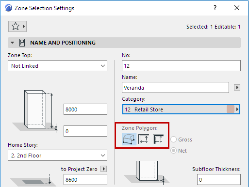
Use the Info Box icon to access the three options of the manual method: Polyline, Rectangular or Rotated Rectangle.
For more information, see Creating Zones.
Zone Polygon Display (Gross/Net): Use these options to set the Floor Plan display of a Zone created with the Reference Line method.
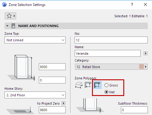
•Net: Zone polygon will not be displayed beyond the inner edge of the boundary walls.
•Gross: Full zone polygon is displayed.
Regardless of the option, the Zone area remains unchanged, only the polygon is displayed differently.
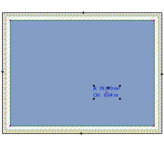
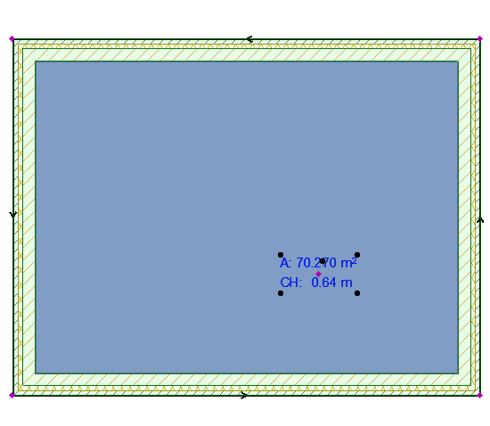
Zone Polygon Net vs. Zone Polygon Gross
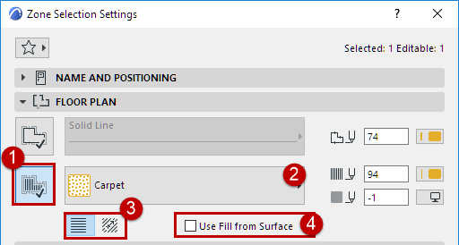
The Floor Plan panel defines the appearance of the Zone’s fill on the Floor Plan.
•Click the button if you want your Zone fill to have an outline.
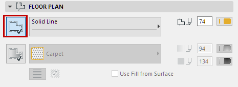
•Choose a Line Type and an outline color from the Line Type and Pencolor pop-up palettes.
•Click the button to choose a cover Fill pattern and background from the Fill pop-up.
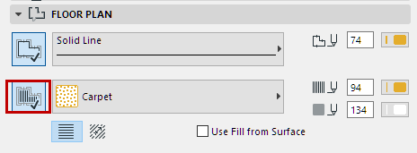
Note: Only those Fills defined as Cover Fills in Options > Element Attributes > Fills dialog box are available here.
For more information, see Assign a Cover Fill.
•Use Fill from Surface checkbox: Zone fill on the Floor Plan will display the same top-side hatching as you set for the Zone’s 3D display in the Zone’s Model panel.
Link Fill Orientation: Choose a method for displaying the vectorial cover fill:
For more information, see Set Orientation of Vectorial or Symbol Fill Patterns.
Use these controls to set the Zone Stamp’s appearance on the Floor Plan.
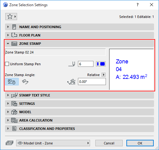
The first field displays the name of the Zone Stamp. You cannot assign a different zone stamp here; the zone stamp shown is the one associated with the Zone Category you chose in the Name and Positioning Panel.
Note: The Zone Stamp assigned to each Zone Category is determined by the settings in Options > Element Attributes > Zone Categories.
Uniform Stamp Pen
Check this box to use this pencolor for all parts of the marker symbol, regardless of any custom colors set elsewhere for this marker.
•Enter a rotation angle for the Zone Stamp.
•Use two icons to define how this angle value should be interpreted when the element is placed:
–Fixed Angle to Screen
–Fixed Angle to Model: Zone Stamp will be rotated along with the view.
See Set Orientation.
For more information on Zone Stamps, see Zone Stamp Panel.
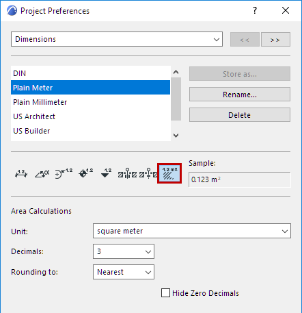
Note: To set the units for the Zone Area display on this Zone Stamp, use Options > Project Preferences > Dimensions, and select Area Calculation units.
Note: Customization of the Zone Stamp parameters will be lost if you change the Category of the Zone. Parameters will revert to the values stored with the Zone Category attributes.
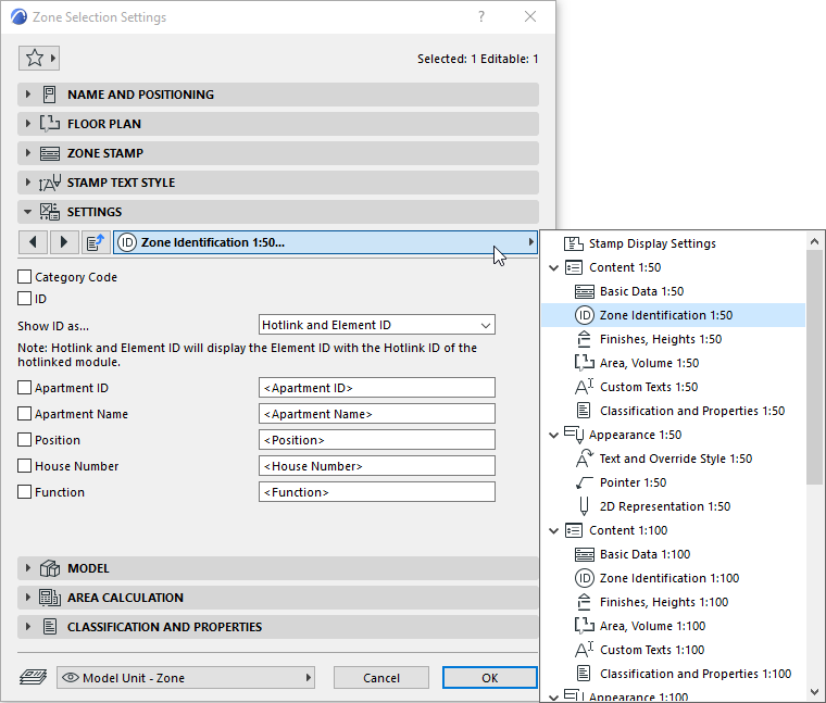
This panel contains additional choices linked to the Zone Stamp.
The Model panel controls the 3D appearance of Zones, including Surface choices and crop options.
Use the pop-up to choose a surface to display this Zone.
•Use this Surface on All Zone Faces: Click this option to display all zone faces of the 3D zone shape using the single surface you selected with the pop-up above.
•Inherit Boundary Walls and Cropping Elements Surfaces: Click this option to have individual surface polygons of the zone inherit the corresponding surfaces of boundary walls and any elements that you cropped the Zone with.
Note: If the Surface has a texture, the texture is automatically aligned to the longest edge of the Zone.
Use the controls in this panel to view the measured area of the Zone and to optionally refine the calculated values.
Note: To see the effect of any changes in Zone calculation settings, you must execute the Design > Update Zones command.
See Updating Zones.
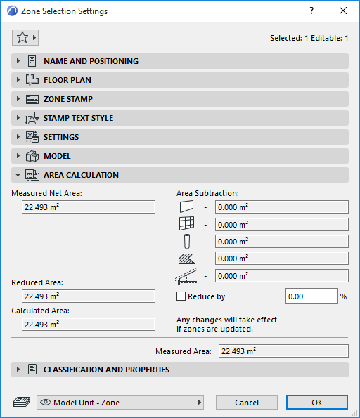
Measured Net Area
The Measured Net Area is the Zone Polygon only up to the inside face of the Bounding Walls. (In contrast, the Measured Area includes the area of bounding Walls all the way to their reference lines.)
Compared to the Measured Area, Measured Net Area is further reduced by Walls, Columns, and/or Curtain Walls that are inside the polygon IF their Relation to Zones is set to „Zone Boundary.”
The Reduced Area results from subtracting the area of certain elements, subject to Zones Preferences, from Measured Net Area.
•Subtract the area of Walls, Columns, and/or Curtain Walls that are inside the polygon IF their Relation to Zones is set to „Reduce Zone Area only.”
–Reduction of these Wall, Curtain Wall and Column areas is further subject to Zones Preferences.
•Subtract the area of Area of Fills if their „reduce Fill area” option is enabled.
•Subtract the area of Area of low ceilings and wall recesses as defined in Zones Preferences
Calculated Area
Click the Reduce by checkbox if you want to further reduce the Reduced Area by any given percentage (enter the desired percentage value in the input field). The result is the Calculated Area.
Area Subtraction
These read-only fields display how much of the zone’s original area is subtracted, depending on elements within or intersecting the zone.
•Walls, Curtain Walls and Columns
Displays the area subtracted for these elements as a result of settings at Options > Project Preferences > Zones.
•Fills
Area subtraction value displays the area subtracted as a result of the Fill’s Subtract from Zones option. (Turn it on or off in Fill Settings - General Settings panel).
•Low ceilings
If the zone is cut by a roof or Shell, displays the area subtracted as a result of settings at Options > Project Preferences > Zones.
Related Topic