Each MEP Route - Duct Route, Cable Carrier Route, and Pipe Route - consists of a hierarchy of the main Route element, plus its sub-elements: segments and nodes.
Each of the Route Settings dialogs reflects this hierarchy. Use the settings pages to set default options for the Route element and its sub-elements.
MEP Calculation Input Data (Duct)
Display of Route Element: Floor Plan and Section, Model Display
MEP Element Custom Settings (Duct, Cable Carrier, Pipe, Elbow, Transition)
As with similar Archicad tools (e.g. Railing), you can customize any particular sub-element. Once a setting is customized and no longer the default, the dialog alerts you that a custom setting is in effect.
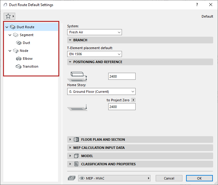
1.Open Route Tool Default Settings
2.On the main Route settings page, choose a System. The MEP System defines the Route’s appearance in 2D and 3D. See MEP Systems.
Note: When you connect a route element to a standalone MEP object, the route element automatically “inherits” the object’s MEP System, instead of using the MEP System set for the route element.
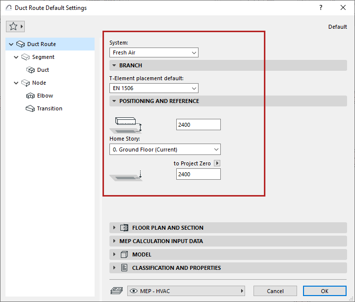
3.Under Branch, the default dimension table is given for the route’s T-elements.
4.Set the Route element’s Positioning and Reference:
•Home story and its offset from that story level
•Bottom offset to the chosen Reference level
MEP Calculation Input Data (Duct)
For a duct route: Enter a Volume Flow limit. The System Browser and Duct Optimizer tool use this information to calculate air flow and resize duct systems.
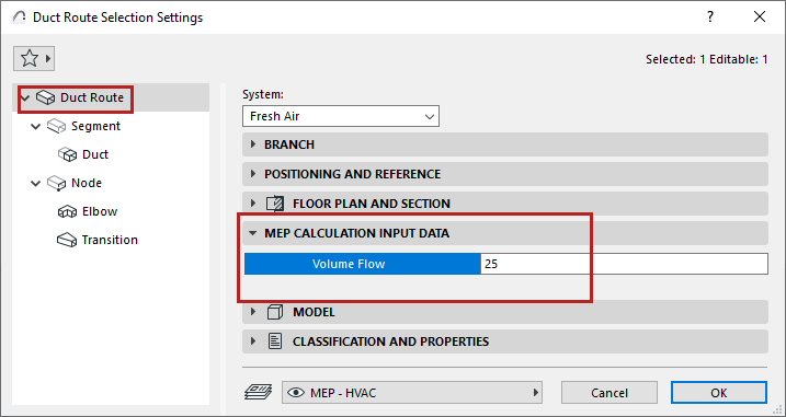
See MEP System Browser (Duct Routes) and Duct Size Optimizer.