Note: Part of the Library Part Maker add-on. See Library Part Maker.
Inside the Design Area, use 2D and 3D tools to draw the components of the Library Part.
Note: It is recommended to consolidate and check the Archicad tools’ attribute settings before you draw or model Library Part definitions. This will help you avoid unwanted attributes as parameters in the Library Part user interface. Setting up your tool attribute settings in the Favorites palette is the best way to minimize errors and avoid the laborious process of checking the tool attribute settings every time.
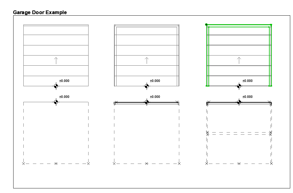
The following example shows the 3D model components in the top row (with LOD increasing from left to right), and the 2D symbols in the bottom row.
Note: To focus on a particular Design Area on the Floor Plan, use the Zoom function from the LPM Palette: see Zoom to a Design Area.

Design Principles for 2D Symbols
•Draw 2D symbol(s) using any 2D Archicad tool (except Text tool).
For a door/window, the 2D symbol orientation must be aligned with horizontal axis (x). The external face of opening should face up (see Examples of 2D Symbol Level of Detail).
•Use Hotspot Tool to define custom 2D hotspots (effective for 2D Symbols only)
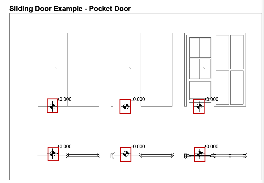
•Assign a content origin to each component (see Define Component Origins (Place Level Dimensions)
•Any Library Parts used in your 2D symbols should be exploded to 2D primitives (lines, arcs, polylines etc.)
Define Component Origins (Place Level Dimensions)
For each component (both 2D Symbol and 3D Model), use the Level Dimension Tool to place a Content Origin. This is used to align the 2D Symbol and 3D Model content when the Library Part is saved.
The origin can be placed at any position as long as it is aligned with other component origins. The recommended approach is to place the origin in the center of an object, or (in case of irregular 2D symbols and 3D models) its bounding box.
The origin must be assigned a component type for each used 2D Symbol and 3D model.
