Loads can be placed on the Structural Member of a load-bearing element, in Floor Plan or 3D view. Therefore, the Structural Analytical Model must be enabled.
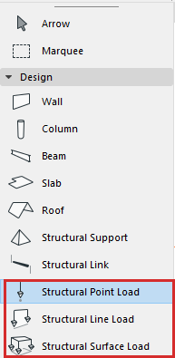
To place a Load, use one of the three Load tools:
•Structural Point Load
•Structural Line Load
•Structural Surface Load
To activate a tool, select it in the toolbox.
Place Point Load
Point Loads can be input on:
•1D Members (node or edge)
•2D Members (node, edge or surface)
1.Activate the Structural Point Load tool.
2.In Tool Settings or Info Box: Select a Load Case (see Load Tool Settings).
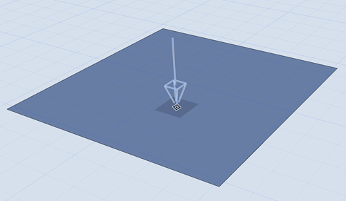
3.While you place the Load element, the potential host element (Structural Analytical Member) is highlighted. You also get a preview of what the Load will look like after placement.
Note: If you are hovering over multiple host elements, use tab to cycle among them until the right one is highlighted.
4.Click to place.
Note: Loads are visible only if they belong to the currently visible Load Case. If you try to place a Load element that does not belong to the currently visible Load Case, you get a notification.

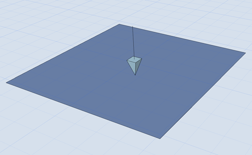
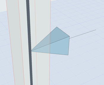
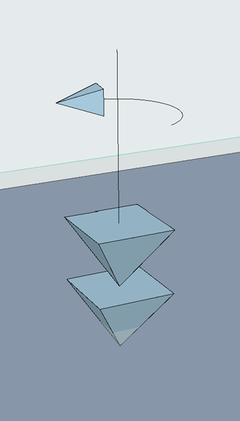
Placing a Point Load
|
|
|
|
Point Force |
Point Moment |
Place Line Load
Line Loads can be input on:
•1D Members (node or edge)
•2D Members (node or edge)
Note: Archicad supports the import (via SAF) of Line Loads placed on surfaces.
1.Activate the Structural Line Load tool
2.In Tool Settings or Info Box: Select a Load Case for your new Load element (see Load Tool Settings)
3.While you place the Load element, the potential host element (Structural Analytical Member) is highlighted. You also get a preview of what the Load will look like after placement.
Note: If you are hovering over multiple host elements, use tab to cycle among them until the right one is highlighted.
4.Click on a Member to specify the start point.
5.Drag the cursor to another node or edge of the same Member to define the line.
6.Click to place the Line Load.
Note: Loads are visible only if they belong to the currently visible Load Case. If you try to place a Load element that does not belong to the currently visible Load Case, you get a notification.
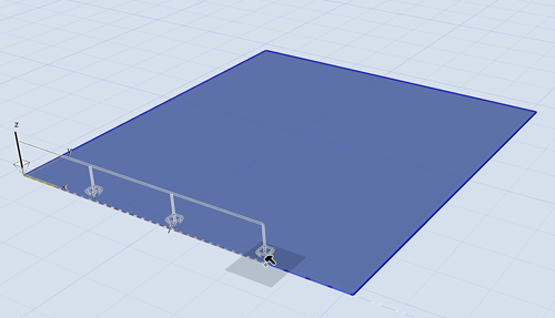
Placing a Line Load
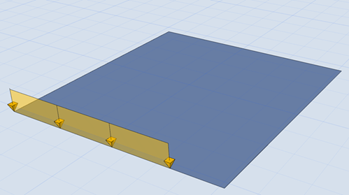
Multiple Line Loads on 2D Member
On a 2D Member polygon: place multiple Line Loads by clicking opposite corners of the polygon.
Click Tab to see previews of alternative Line Load paths

Click Tab to See Alternative Placements
Click to place:

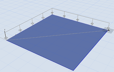
Line Loads on All Edges (Shortcut)
Use space + click to create Line Loads on all 2D Member edges.
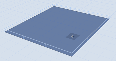
Place Surface Load
Surface Loads can be placed on the entire surface of a 2D Member.
1.Activate the Structural Surface Load tool
2.In Tool Settings or Info Box: Select a Load Case for your new Load element (see Load Tool Settings)
3.While you place the Load element, the potential host element (Structural Analytical Member) is highlighted. You also get a preview of what the Load will look like after placement.
Note: If you are hovering over multiple host elements, use tab to cycle among them until the right one is highlighted.
4.Click to place the Surface Load.
Note: Loads are visible only if they belong to the currently visible Load Case. If you try to place a Load element that does not belong to the currently visible Load Case, you get a notification.
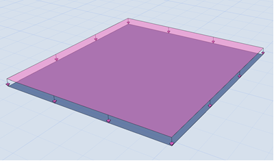
Placing a Surface Load
You can also generate live loads automatically on zones.
See Generate Live Loads.