The panels of the Skylight Tool Settings dialog box are similar to those of other Library Part elements.
See Settings of Library Part Elements.
For more information, see Skylights.
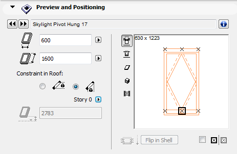
Skylight Preview and Positioning Panel
Height: Enter Skylight height.
Constraint in Roof: Only available for selected Skylights placed in Roofs (not Shells). Use this control to decide how to constrain the Skylight position in a modified Roof plane:
•either Horizontally (the Skylight will retain its position as seen on the Floor Plan)
•or Vertically (the Skylight will retain its vertical elevation regardless of its Floor Plan position.)
For more information, see Skylight Constraint Relative to Roof.
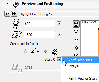
Sill or header height: This field that expresses the height of the Skylight anchor point (either its sill or header) as measured from either a particular story, or from the Roof Pivot line. (If you have constrained the Skylight position horizontally, this field is read-only.)
•Click on a hotspot the Preview window to define the Skylight sill/header anchor point (at the top or bottom of the Skylight).
•From the pop-up, choose whether to measure this height from a particular story, or the Roof pivot line.
The Flip in Shell button is only available for selected Skylights placed in Shells (not Roofs). Click Flip in Shell to change the orientation of the Skylight to the opposite side (e.g. from “inside” to “outside”.)
Check the Mirror Library Part box to mirror the Skylight when placing it, or to mirror a selected Skylight.
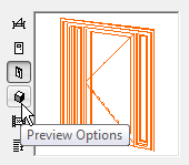
Preview Options
The Preview Area at the right shows you the Skylight in different displays, depending on which of the five icons (at left) that you choose. As you set different parameters for the Skylight, keep an eye on this preview to see the effects of your edits.
Click among the Preview Options to vary the preview picture:
Move the cursor inside the Preview Area and the cursor will change to a “flip” arrow, allowing you (in the 2D Symbol or 3D views) to alternately view each side of your Library Part.
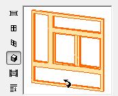
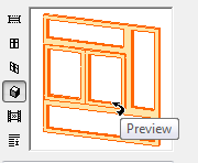
The preview options, from top to bottom:
•2D symbol
•hidden line front view
•hidden line axonometry
•3D shaded axonometry
•predefined preview picture
Note: To modify the predefined preview picture, use the Preview Picture controls in the GDL Object Editor.
See Preview Picture.
Move the cursor inside the Preview Area and the cursor will change to a “rotate” arrow, allowing you (with successive clicks) to rotate the 2D Symbol or 3D View of your Library Part.
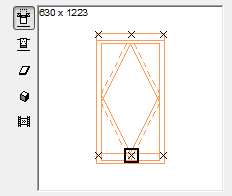
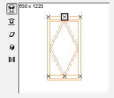
A Skylight is positioned by its hotspot, defined in the 2D symbol of the Library Part.This hotspot is marked with a highlighted rectangle, and it will act as the insertion point and anchor point for the Object.
The other hotspots (if any) are displayed as X’s. Click any of them if you wish to use it as an insertion/anchor point instead of the default primary hotspot.
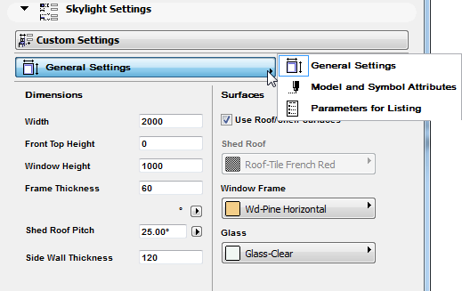
Use either this list or the Custom Settings graphical interface to set Skylight parameters.
Note: Fill and pencolors for Floor Plan display can be defined either in this Parameters panel (using the 2D Representation controls), or else overwritten by entering custom fills and pens in the Floor Plan and Section panel below.
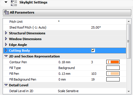
Click any of the parameters to select it and to modify the value of the variable.
Skylight Custom Settings
Use this interface to set parameters for the Skylight. (Alternatively, use the All Parameters list format.)
Skylight Floor Plan and Section Panel
On the Floor Plan, Skylights are, by default, based on a 3D projection, not a symbolic depiction.
Note: Skylights in Single-plane Roofs that were migrated from ArchiCAD 14 or older version projects can be displayed, if you prefer, using a Symbolic depiction.
See Legacy Preferences.
The controls in this panel define the line types and pen colors of Symbol lines and Outlines (both Uncut and Overhead), and Cut Lines and Fills for the Skylight.
•Enable Object’s Linetypes
•Enable Object’s Pens
These checkboxes in the Floor Plan Display Panel allow you display the Skylight using the relevant parameters, if any, (e.g. pens, fills) which have already been defined for the Skylight.
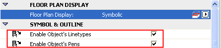
However, to override these parameters, uncheck the “Enable Object’s” checkbox and set custom display options.
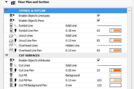
If no such parameter is defined for the Skylight, then checking the box will have no effect; the object will be displayed using the attributes defined in the Floor Plan and Section panel, as follows:
•Symbol Line, Pen
•Uncut Lines, Pen
•Cut Lines, Pen
•Overhead Lines, Pen
•Cut Fill, Pen, Background Pen
Skylight Dimension Marker Panel
The Dimension Marker panel features the customizable options for the Skylight’s Dimension Marker.
To show or hide Skylight markers on the plan, use the Skylight Options in Document > Set Model View > Model View Options.
For more information, see Model View Options for Construction Elements.
Dimension Markers are essentially parametric GDL objects permanently linked to the opening.
The dimension units of Skylight markers can be customized in Options > Project Preferences > Dimensions.
For more information, see Dimensions Preferences.
From the pop-up list, choose a predefined Marker or browse for a different marker object.
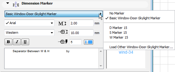
The preview window gives you feedback on the selected Marker’s appearance.
Pencolor/Penweight: Type a Pencolor/Penweight number (1-255).
Use Symbol colors: Check this box to ignore Pencolor setting above and use pencolor used when the element’s 2D symbol was created.
Subfloor Thickness: Use this control if you want the Skylight marker to indicate a sill height value which takes into account the height difference (if any) between the story level and the sill of the Skylight (e.g., to account for carpeting). This value will then be calculated as part of the sill value shown in the Skylight marker.
See also Sill or Header Heights.
This value will not affect the positioning of the Skylight.
Font Type: Click this pop-up field to select a font type.
Font Script: Click this pop-up field to select a font encoding.
Font Size: Enter a font size.
Text Format: If desired, check the Bold, Italic, or Underline boxes to format the dimension text accordingly.
Height: Enter the height of the marker here.
Skylight Custom Marker Settings Panel
The Marker Settings panel contains options for the Library Part type dimension marker. The panel is active only if an eligible Marker has been selected in the Dimension Marker panel.
Skylight Listing and Labeling Panel
See Listing and Labeling Panels.
Skylight Tags and Categories Panel