Translators for Export (Detailed Settings)
An IFC Translator for Export defines the rules for handling model elements exported from ARCHICAD to an IFC format.
For an overview of this topic, see IFC Translators: Overview.
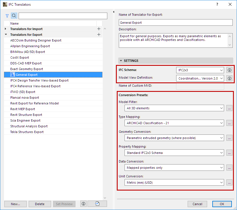
The IFC Translators dialog box (File > Interoperability > IFC > IFC Translators) allows you to view or modify Translator settings, or to create new Translators.
Select a Translator for Export from the list.
The selected Translator’s settings, divided into six Conversion Presets, are shown on the right side.
One of the Translators for Export is the Preview Translator. The Preview Translator exists to provide default mapping definitions needed to work with IFC data in ARCHICAD.
For details, see Preview Translator.
The IFC Schema and Model View Definition categories help in setting up presets that are compatible with particular standards (see details below).
IFC Schema (Translators for Export only)
An IFC Schema is a particular version of the IFC standard. ARCHICAD Translators can support either Schema IFC 2x3 (recommended) or IFC 4.
Note: IFC 2x3 is recommended - this is the most widely used version. Choose IFC 4 only if you are certain that it is supported by the application that will receive IFC data using this Translator.
Model View Definition (Translators for Export only)
A Model View Definition (MVD) is a recommendation for which data and elements the IFC model should include, depending on the purpose of the model exchange. If your exported IFC model must conform to a predefined standard MVD, choose that MVD from the list.
Note: Available MVD’s depend upon the IFC Schema chosen above: IFC 2x3 or IFC 4.
For a more detailed explanation of MVD’s and their characteristics, see Model View Definitions.
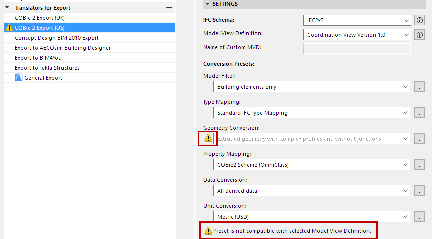
Once you choose an MVD, then certain Translator for Export settings must conform to the requirements of that MVD. If you change a Translator setting so that it no longer conforms to the selected MVD’s requirements, then the Translator becomes invalid, and you get a warning in the dialog box. The problematic setting is also marked:
Working with Conversion Presets
For any category of Conversion Preset, click the dropdown list to view or select a different Preset. The Preset name gives you an idea of how it will affect the exported IFC model, if this Preset is used in a given IFC Translator for Export.
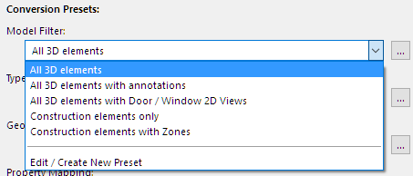
Choose a different preset from this list if needed.
To adjust settings or create a new preset, select Edit/Create New Preset, or click the three buttons at the right of the Preset.
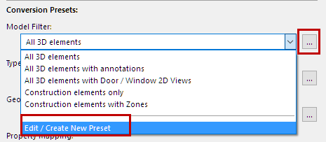
The Preset dialog opens (for example, the Geometry Conversion for IFC Export).
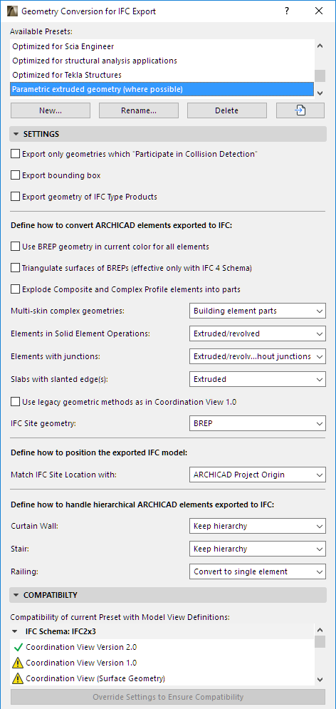
For each of the IFC Export Preset dialogs, view the following:
•Available Presets for this Conversion process (e.g. Geometry Conversion)
•Settings (this is where the export is defined in the greatest detail, for various data types, as defined for the currently selected preset at the top)
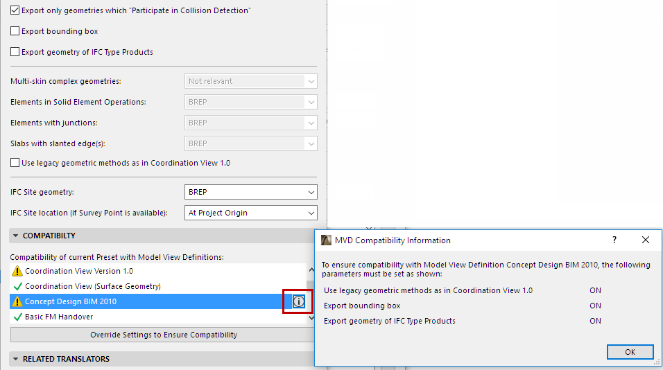
•Compatibility: Feedback on whether the current settings of this preset conform to particular Model View Definitions.
Click the info button to see the settings conflicts, if any. If the current Translator for Export does not use that particular MVD (e.g. Concept Design BIM 2010), then this conflict need not be a problem. To ensure compatibility with the MVD, you can adjust the settings as shown in the Info dialog, or just click the Override Settings button to solve the issue.
•Related Translators (all the currently defined IFC Translators for Export which use this Preset)
All Settings of each type of Conversion Preset (used by IFC Translators for Export) are detailed in the following sections.
Geometry conversion for IFC Export
Property Mapping for IFC Export
Data Conversion for IFC Export
IFC Global Unique Identifier Attribute (GlobalId)
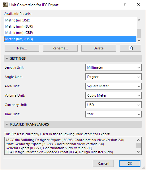
Unit Conversion for IFC Export
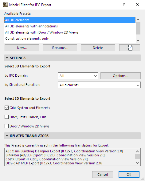
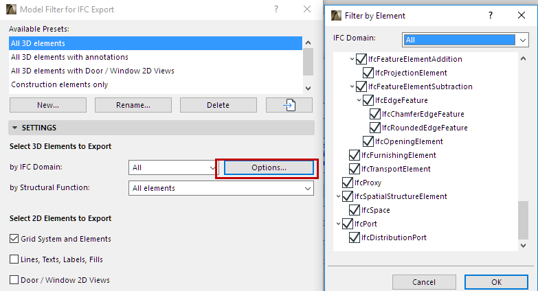
Select 3D Elements to Export
This filter defines which ARCHICAD 3D elements should be exported to IFC. You can filter by the elements’ IFC Domain and/or by their Structural Function.
Note: An element’s IFC Domain depends on its Type Mapping preset.
◦“All” includes all elements from the model
◦“Structural” includes only the structural building elements
◦“MEP” includes only the mechanical elements (IfcDistributionElement).
To see the exact composition of each Domain filter, click “Options” to open the Element Filter dialog box. Modifying this filter will create a “Custom” filter.
•By Structural function
This is an additional filter to the IFC Domain filter set above.
-This filter considers the ARCHICAD element’s “Structural Function” category: Either Load-Bearing or Non-Load Bearing. This is set for each element in its Classification and Properties panel of Element Settings.
- “Load-Bearing elements only” means that only those elements classified as “Load-Bearing Element” (plus ARCHICAD Zones) will be exported from ARCHICAD to IFC.
•Grid System and Elements: Check this to include the Grid Elements and the grid members of Grid Systems in the exported file.
Grid elements will show up in the IFC structure as IfcGrid.
•Lines, Texts, Labels, Fills: Check this to export these 2D elements, plus all dimension types.
2D elements will show up in the IFC structure as IfcAnnotation. Dimensions will be exploded into lines and texts, since the IFC 2x3 standard documentation does not include a dimension element.
Note: The inclusion of 2D elements in the exported file is also affected by the “Elements to Export” filter at “IFC Save Options”: if a 3D view is currently active, the 2D elements can be included only if the “Entire project” option is selected in that filter. (See Filter Model at Export.)
•Door/Window 2D Views: Check this box to include the 2D symbols of doors and windows in the export process, in addition to 3D model geometry. This is handy if the recipient program recognizes these data and can correctly display, for example, the door opening directions.
From this preset dialog, click the Map IFC Types for Export to access the mapping definitions.
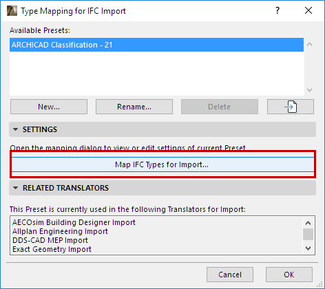
When a model is exported to IFC format, every one of its elements is assigned an IFC Type.
For further definition, see IFC Type.
This dialog defines how to assigns an IFC Type to each exported ARCHICAD element. There are two methods: By Element Type, or By Classification.
Note: The Type Mapping preset of the Preview Translator has an additional function: to define the default IFC Type classification of elements in the current ARCHICAD project.
See also Preview Translator.
Watch the Video:
Element Classification: IFC Conversions and Properties
Mapping by Element Type
Assigns each ARCHICAD Element Type automatically to a default, basic IFC Type, corresponding to its ARCHICAD tool or (for GDL objects) to its Object Subtype.
If you choose this method, no further manual mapping is needed. The rest of the dialog controls are inactive.
For more details, see Built-in IFC Element Type Mapping for ARCHICAD 21.
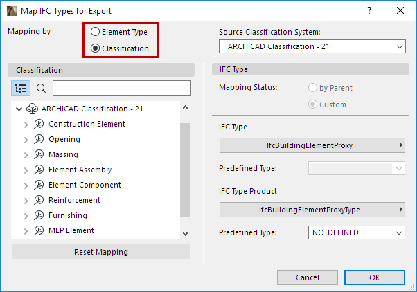
Mapping by Classification
Maps each ARCHICAD Classification to an IFC Type, Type Product, and/or Predefined Type. This method allows for flexible and detailed IFC Type classification, according to specific IFC standards.
Source Classification System
Choose a Classification System (among those defined in the ARCHICAD project) to display its classification structure in the tree at left.
The Classifications of the selected System are now listed at left. Select each one to map it to an IFC Type (on the right), to be assigned to classified ARCHICAD elements at export.
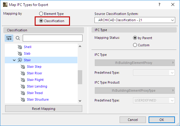
Mapping Status by Parent
Maps the selected Classification to the same IFC Type as its parent Classification. For such Classifications, you don’t have to define the IFC Type, because it will automatically get the same one as its parent.
Mapping Status: Custom
Maps the Classification to an IFC Type selected by you. This allows you to assign more specific IFC Type assignments to the exported elements.
If the chosen IFC Type or IFC Type Product have Predefined Types, you can map those too.
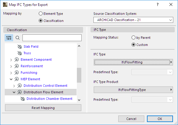
Reset Mapping
Click this button to undo the mapping definitions made since opening the dialog.
Geometry conversion for IFC Export
These settings define how to convert the geometry of ARCHICAD elements exported to IFC.
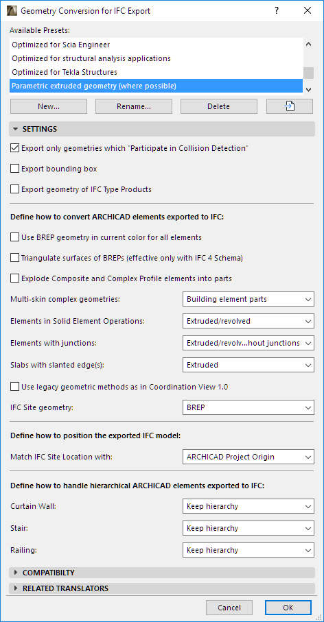
Export only geometries which “Participates in Collision Detection”
Exports only elements whose ARCHICAD Building Material includes the “Participates in Collision Detection” option ON. (This is set at Options > Element Attributes > Building Materials > Properties).
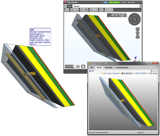
Use this option to export composite elements and complex profiles, which don’t have solid geometries, as real air gaps. This way, MEP engineers (who receive the ARCHICAD IFC file) can place pipes in the gaps without collision detection; only element parts which have real geometry will participate in collision detection.
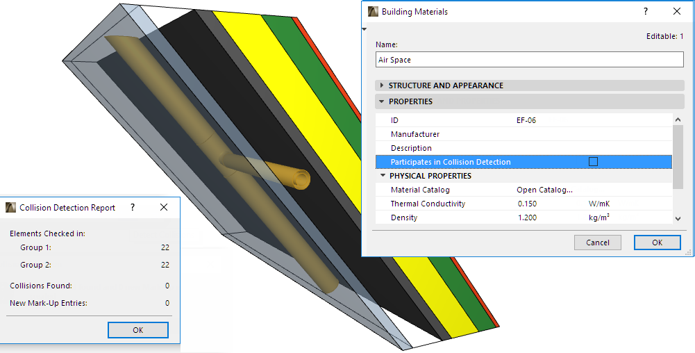
See also Collision Detection.
Exports the dimensions of the building elements’ bounding box.
Export Geometry of IFC Type Products
Assigns a representative geometry to each Type Product. (This option is required for Concept Design BIM 2010.)
Each type (e.g. IfcFurnishingElementType) will use a representative geometry of the elements that belong to it (e.g. IfcFurnishingElement).
Use BREP geometry in current color for all elements
All model elements are exported using BREP (Boundary Representation) geometry. BREP is precise but non-parametric geometry.
The elements will be exported in the color displayed in the current ARCHICAD view, including colors defined by Graphic Overrides, Renovation Status, and Mark-Up Corrections or Highlights.
Triangulate surfaces of BREPs (effective only with IFC4 Schema)
BREP geometry is saved as triangulated surfaces - an option preferred by some model visualization applications when importing IFC files. This option - which only works if you are using the IFC4 Schema - produces a compact geometrical description, which might reduce file size.
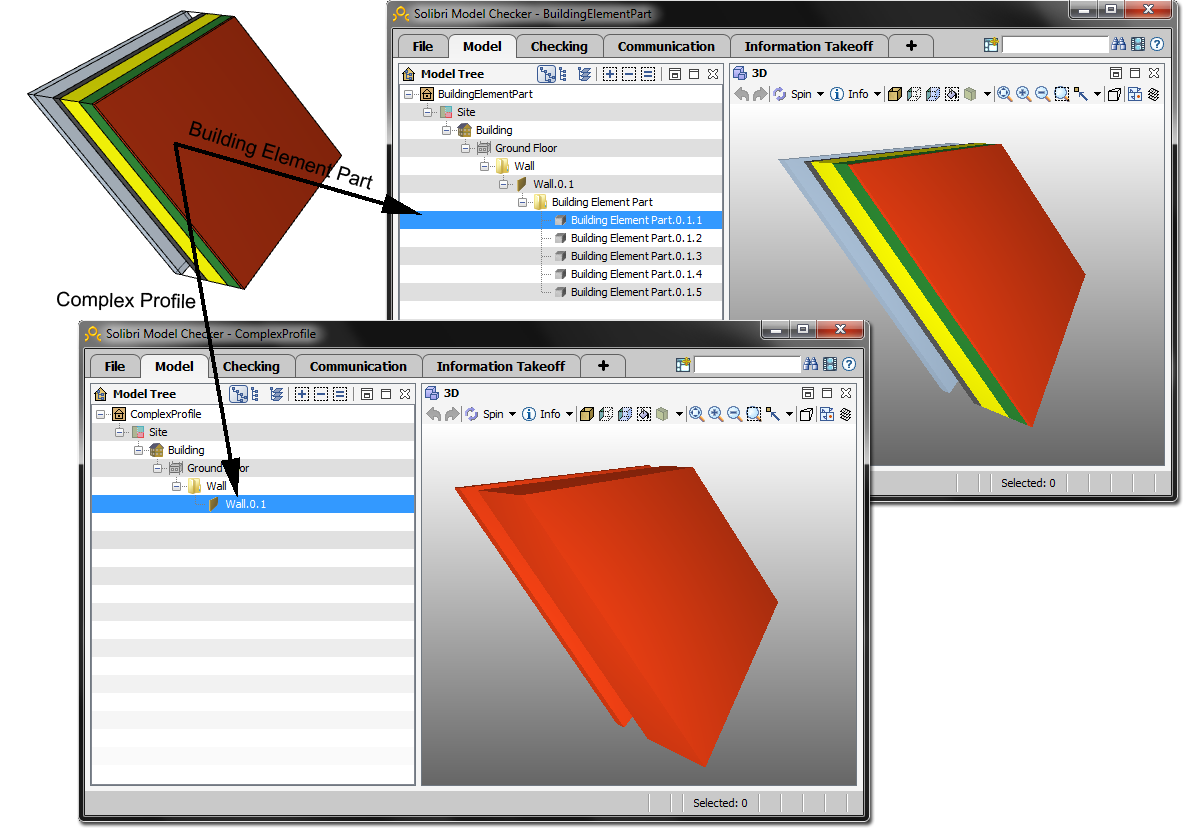
Explode Composite and Complex Profile elements into parts
Saves composite elements and Complex Profiles as so-called “Building Element Parts”. This means that the main element (e.g. IfcWall) will be saved as a Container element without geometry, and its parts (the skins or profile components) will provide the geometry.
This export option retains the original colors of all building parts, instead of exporting the element in all one color.
Note: Not applicable if “Explode Composite and Complex Profile elements” box is checked, above.
Choose how to handle components of multi-skin, complex elements exported to IFC.
This option affects multi-skin (Composite or Complex Profile) ARCHICAD elements having complex (e.g. slanted) geometry representation.
•Building element parts: Creates multiple sub-elements, each with its own geometry and material information. Each sub-element is assigned the IFC material or profile that is represented by its Building Material (Cut Fill) in ARCHICAD.
•Complex profiles: The complex geometry is converted to a single IFC element with a profile geometry and an IFC material. (The receiving application will not know the precise order of the different components/skins.)
Note: This option is affected by the “Partial Structure Display” (Document menu) currently in effect in ARCHICAD, if the view’s visible elements are being exported. For example, if the exported model uses “Core Only” display, then the “Complex profiles” option will have no effect on a slanted composite wall with a single core, because the visible wall consists of a single core skin.
Elements in Solid Element Operations
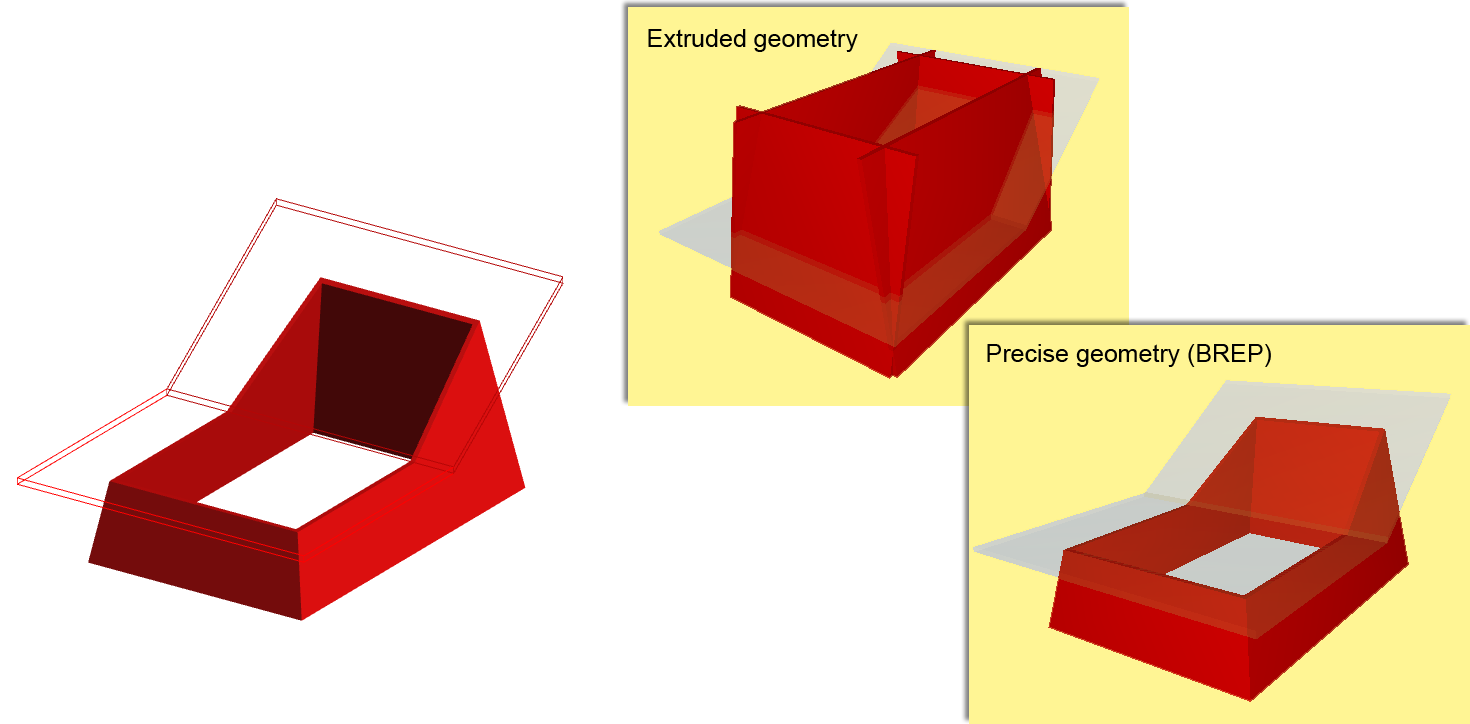
•Extruded/revolved: This method retains the elements’ parameter values (such as thickness, height, location of reference line or edge, skin structure of composite materials). However, certain specialized sections are not retained.
This is the format usually supported by static analysis programs, in which element parameters are important, but their special cut angles (such as the slanted edge of a slab) are not important.
•BREP: This method provides the most exact reproduction of element geometry, together with its specialized sections and connections. However, the element’s parameters are lost, and BREP (Boundary Representation) elements are transformed into non-editable elements. This method is useful in the “reference model” workflow.
•Extruded/Revolved without junctions: Elements are exported without the priority-based intersections, resulting in a faster export process. This option is recommended for structural analysis programs, for which the elements’ reference lines/surface information is sufficient, and detailed intersections are not required.
•BREP: Elements are exported together their junctions, for precise geometry.
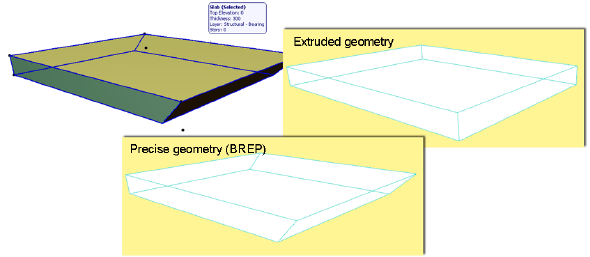
The difference in the two export methods is illustrated here:
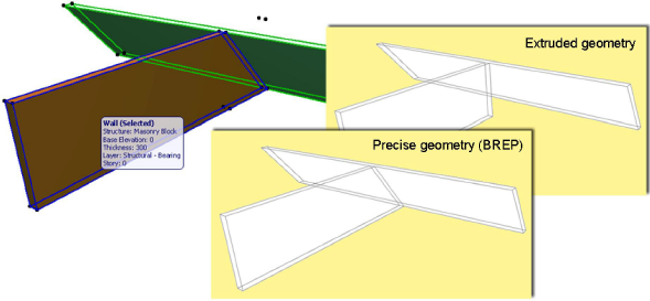
•Extruded: Slabs will be exported with vertical edges (even though their original geometry included a slanted edge.)
•BREP: Slabs will be exported with precise geometry, recreating the slanted slab edges.
Use legacy geometric methods as in Coordination View 1.0:
•Use this option if you have created your own, custom MVD that is based on the geometry methods of Coordination View version 1.0.
Choose how to represent ARCHICAD Site Geometry exported to IFC.
ARCHICAD elements will be considered Site Geometry if they are classified using “IfcSite” as their IFC Type. (See Type Mapping for IFC Export.)
Note: If you are mapping by Element Type instead of by Classification, save the element as an Object having the Subtype “IFC Site”.
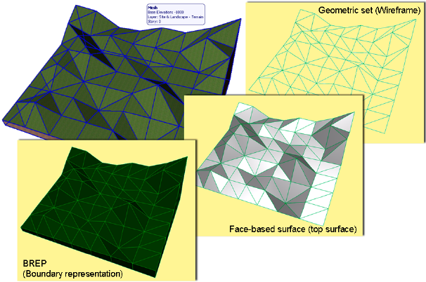
Choose one of the following site geometry methods, depending on which one the receiving application can read:
•BREP: Geometric representation as solid bodies, enclosed by their superficies and boundary surfaces. All faces are planar and all edges are straight lines.
•Face-based surface (top surface): Geometric representation of the superficies (top surface) only.
•Geometric set (wireframe): Geometric representation with contours and points.
Note: ARCHICAD can import all three of these IFC site geometry representations.
Define location of the IFC Site entity (its coordinate system), if a Survey Point has been defined in ARCHICAD. (See also Using Survey Point in ARCHICAD, below.)
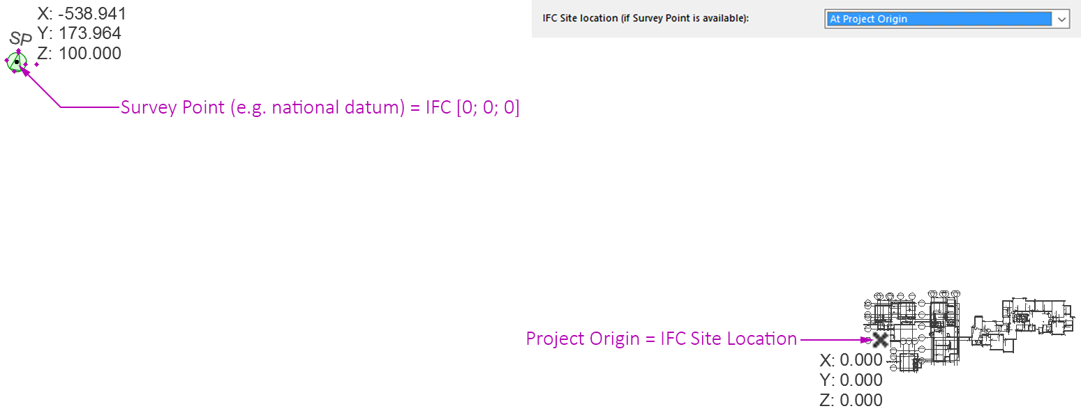
•ARCHICAD Project Origin: Locate the IFC Site entity at the Project Origin if you are working close to the ARCHICAD Project Origin, yet still wish to define model coordinates relative to a national datum (using the Survey Point). This way, a far offset is stored in the IFC file not as part of the element coordinates, but rather generally. See the following illustration:
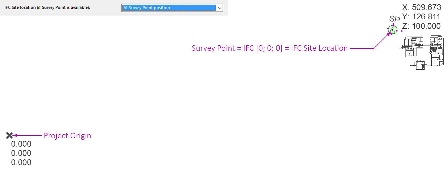
•ARCHICAD Survey Point position: Locate the IFC Site entity at the position of the Survey Point. Use this if you are working at a long distance from the Project Origin, yet you don’t want large offsets to be present in the IFC file (usually with legacy models). See the following illustration:
Notes:
◦If the ARCHICAD project does not contain a Survey Point, then the IFC model’s global coordinate system origin will be the ARCHICAD Project Origin. The IFC Site location will be located either at the Project Origin, or - in case of long distances (approximately one-kilometer coordinates) - at the Center of Weight of Model calculated by the program. Use this option if your earlier models contain elements at long distances (legacy issue). With new projects, the Survey Point option is recommended.
◦If the ARCHICAD project contains multiple Survey Points (though it is recommended to use just one), then the first placed Survey Point will be used. (A warning will alert you to this.)
◦The program will consider the Survey Point even if it is not visible in the exported view (i.e. if it is on a hidden layer)!
Using Survey Point in ARCHICAD
ARCHICAD has a Survey Point object, which can be used as common reference point to facilitate coordination of models from different programs. In some countries, use of a particular reference point is a standard requirement when defining the project.
The position and rotation of the Survey Point defines the global coordinate system (X=0, Y=0, Z=0) of the IFC model. When defining this point position in ARCHICAD, it is recommended to consider the True North direction (use the default “Follow Project North” parameter). At IFC export, this parameter defines the direction of the Y axis in the global coordinate system.
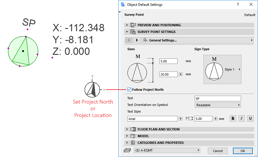
Notes:
◦In ARCHICAD, True North is defined by Project North (Options > Project Preferences > Project Location)
◦The Survey Point is always created at IFC Open. In case of Merge IFC, the model is imported to be aligned to the host file’s Survey Point.
For more information on Survey Point in ARCHICAD, see the Help Center article at: http://helpcenter.graphisoft.com/tips/open-bim/survey-point-is-now-supported-at-ifc-importexport/.
Mapping IFC Location Data From ARCHICAD and Revit
|
IFC |
ARCHICAD 20 and up |
Revit |
|
IFC Global Origin |
Survey Point |
Survey Point |
|
Position of IfcSite entity |
Project Origin |
Project Base Point |
Hierarchical ARCHICAD Elements Exported to IFC
Define how to handle Curtain Walls, Stairs and Railings exported to IFC:
•Convert to single element: The hierarchical element is exported as a single IFC entity, which contains within itself the geometry of all its sub-elements. The hierarchical nature of the original element (e.g. Stair, with all its separate sub-components) is thus lost.
•Keep hierarchy: Retain the original element’s hierarchical structure, including sub-elements.
See also Exporting Hierarchical Elements from ARCHICAD as IFC Containers.
Property Mapping for IFC Export
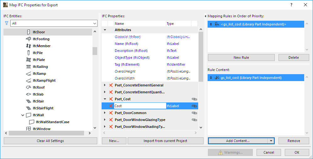
From this preset dialog, click the Map IFC Properties for Export to access the mapping definitions.
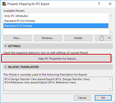
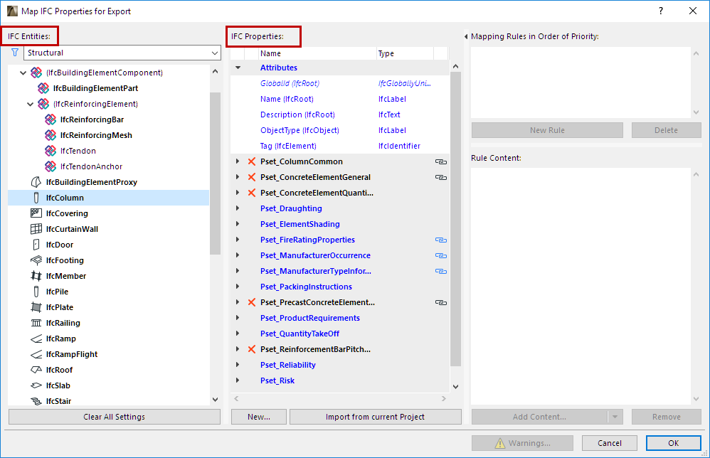
These mappings define the IFC properties assigned to elements when exported from ARCHICAD. Elements (identified by IFC entity) are listed in the tree at left. The IFC Properties of each selected entity are listed in the IFC Properties column.
In addition to the predefined IFC properties for each IFC entity, you can create and assign new custom IFC Properties or Classification References.
In the IFC management dialogs, Mapping Preset data are shown with a checkbox in front of them. In contrast, custom data are shown with a red X in front. Mapping Preset properties cannot be deleted in either the Settings dialogs or in IFC Project Manager; you can only set their values there.
To map data automatically, use the optional Mapping Rules to assign values to IFC Properties.
See Examples of Property Mapping Rules, below.
The Property Mapping preset of the Preview Translator has an additional function: to provide the default set of IFC Properties used while working with IFC-related functions in the current ARCHICAD project.
See also Preview Translator.
Note: In previous ARCHICAD versions, these settings were project-specific, and managed in IFC Scheme Setup. For information on migrating IFC Schemes to ARCHICAD 21, see: Migrating IFC Settings in the Migration Guide.
Tree list of IFC Entities
IFC Entities are listed in the tree at left.
•IFC Entities which have property data assigned to them are listed in the tree in bold type.
•The tree list can be filtered by Structural and MEP domains. For example, the Structural domain contains the building element (IfcBuildingElement) types (IfcBeam, IfcColumn, etc.) while the MEP domain contains the IfcDistribution types.
•The tree list can also be narrowed to the IFC Assignment types, IFC Type Objects, or IFC Spatial element types (IfcSpatialStructureElements: IfcSite, IfcBuilding, IfcBuildingStorey and IfcSpace).
Add New Property/Classification Reference
To add a new IFC Property or Classification Reference data to the currently selected Entity, do one or both of the following:
•Click the New button to create a New Property or Classification.
The same function is available in the IFC Project Manager and Element Settings dialog boxes.
See Create New, Custom IFC Property or Classification.
•Import from Current Project: Click this button to add all the custom IFC Property Sets and Properties (defined in either IFC Project Manager or Element Settings) that are available in the current Project.
List of IFC Properties
•BOLDFACE: Property data assigned to a bold parent element (such as IfcBuildingElement) are automatically assigned to all its child elements (e.g. IfcBeam, IfcColumn, IfcSlab, IfcWall, etc.) The child element will not be shown in bold type. This way it is easy to locate, in the tree structure, where the data were added.
•BLUE TYPE: Data assigned to a child element are shown in blue type. This data can be modified only at the parent level (which is in black). The child element’s name is augmented by the parent type name in parentheses.
◦Thus, to create a common property for all building elements, you don’t have to create it for every single building element type (IfcWall, IfcColumn, IfcSlab, etc.): instead, create it once at a higher level (e.g. at IfcBuildingElement).
•GREY: Properties shown in grey are mapped but not editable, because there is a 1-to-1 mapping relationship with ARCHICAD parameters. Examples: the “Renovation Status” (same as the Renovation Status in ARCHICAD); the “LoadBearing” (same as Structural Function in ARCHICAD); and the “IsExternal” (same as ARCHICAD Position Category items).
•ITALICS: A new data item is shown in italics if no ARCHICAD parameter/quantity or mapping rule can be applied to it.
•Chain icon: Indicates that the property is mapped. View its mapping rule at the right side of the dialog box. Blue mapped properties cannot be edited (they are derived from a higher-level item).
•X: Delete any data item by clicking the red X. Attributes cannot be deleted.
Clear All Settings
Delete the entire contents (mapping rules, Properties and Classification References) of the current Property Mapping Preset.
Import from Current Project
Click this button to synchronize all changes (name and value type modification, and data mapping) in the IFC Project Manager and Settings dialogs for properties that already exist.
If a property assigned to an IFC element type (for example IfcWall) is not yet available in the current project, it is not displayed in the IFC management dialogs until one instance of the type has been defined in the model.
If you have a new empty project, the Preview Translator’s Property Mapping data are used as initial IFC data.
Advantages of data mapping:
•You don’t have to enter those data twice (once as ARCHICAD data, and again as IFC data) which have a common meaning as both ARCHICAD data (e.g. Fire Rating) and IFC (FireRating).
•You can save ARCHICAD data as a specific IFC model in accordance with a particular standard (e.g. COBie documentation or company standard), a particular collaborative workflow (e.g. MEP, energy analysis, FM), or the capabilities of a particular IFC model receiver application (e.g. Revit, Tekla, Allplan...).
The following IFC elements listed in the Property Mapping tree and their sub-elements (called “child” elements) are mappable:
•IfcElement (building, distribution, furnishing and transport elements),
•IfcSpace (ARCHICAD Zone)
•IfcTypeObject (including all IFC Type Product entities).
Mapping works for ‘single value’-type IFC Attributes and Properties only. Thus:
•it works for all text-, label- and logical-type properties,
•it does not work, for example, for ‘table-type’ properties,
•it does not work for Classification Reference data.
A mapping rule can be assigned at different levels. For example, you can apply a rule at the IfcBuildingElement level, which will be applicable to all of its child elements (e.g. IfcWall, IfcSlab, etc.). However, the mapping rule (which appears in blue type at the child element’s level) can be redefined at the child level. For example, the abovementioned rule could be modified for the IfcWall entity.
If a particular parameter is common to several Library Part elements, you can map its corresponding IFC data in just one step (see examples later).
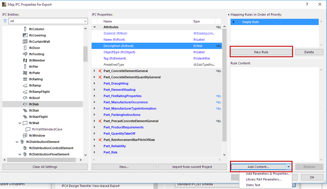
1.Select the IFC Property which you would like to map. Data in italic type cannot be mapped.
2.Click on the “New Rule” button. The “Empty Rule” field appears.
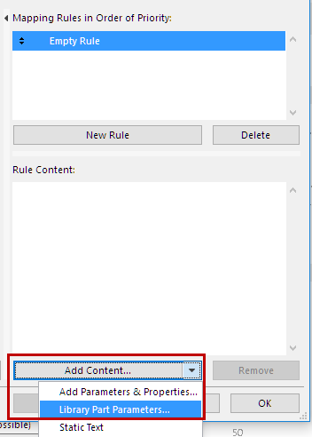
3.from the “Add Content” drop-down button, select a Rule Content type:
◦Parameters & Properties (as the Interactive Element Schedule)
◦Library Part Parameters (as the Interactive Element Schedule)
◦Static Text
4.Add fields to the rules. Fields can have types: e.g. “Thickness” is length measure, “Area” is area measure, “Library Part Name” is string. If a rule contains more than one field, the fields are always a concatenation of fields converted to a string. Conversion is based on calculation units (Project Preferences > Calculation Units & Rules). Fields implicitly contain filters: for example, the Wall's “Height” field can only be evaluated for Wall elements. “General” fields are listed at tool levels too and are valid only for that specific tool.
5.Library Part Parameters can be set in two ways:
◦Library Part dependent: The selected Library Part parameter will be in effect only for elements that contain this parameter. If the Library Part parameter was defined at the Object subtype level, then the parameter mapping will take place for the child elements, too. For example, if we are mapping the “gs_list_cost”variable parameter of the GS Door Object subtype, then the mapping will be in effect for all Doors (and ifcDoors) which are child Library Part elements of the GS Door (such as Door, Double Door, Metal Door, etc.) See examples below.
◦Library Part independent: the parameter variable (e.g. “gs_list_cost”) will be in effect for the mapping, regardless of which Library Part it was chosen from. For example, if you select the “gs_list_cost” parameter of the Double Door for mapping as a Library Part Independent parameter, then the mapping will take place for every Door that accesses the “gs_list_cost” parameter. If this door parameter is used for mapping at the IfcElement level, then it will be mapping for all IFC entities which are child entities of the IfcElement and which include the “gs_list_cost” parameter (such as Furnishing elements, e.g. Armchair and Chair). See examples below.

Note: If the Property Mapping Preset Setup contains a mapping rule involving a Library Part parameter which is not loaded in the project, then the rule, the mapped IFC data, and the mapped IFC Entity data are all shown in red.
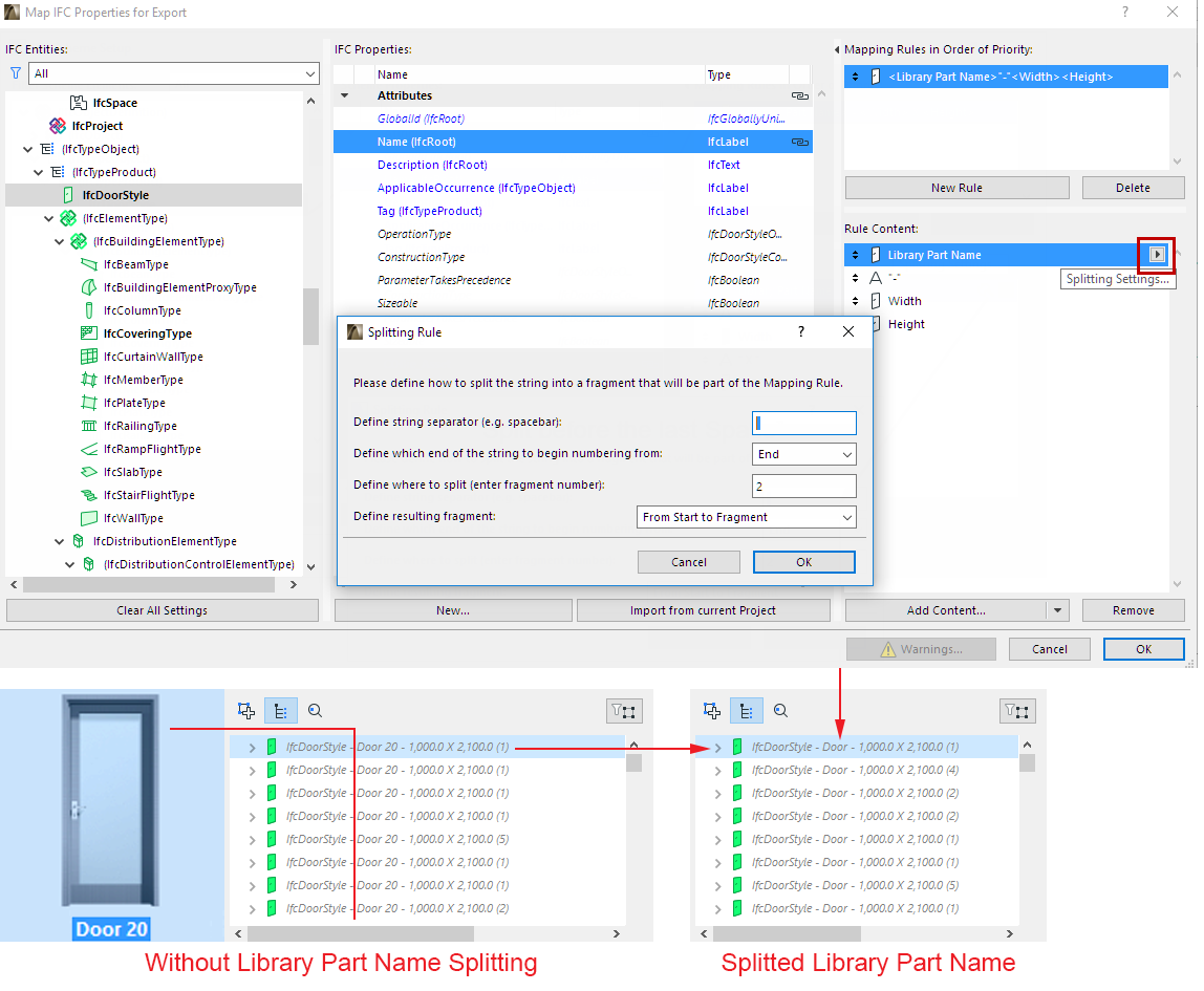
6.String-type rules can be split. Separator type, separator position and split type give you several ways to split a string. For example, use a split to cut out a particular fragment of a Library Part Name.
You can assign multiple rules to a single property. This is useful, for example, if several tools will generate the same IFC element type. Rules will be applied in the order in which they appear on the user interface: the first valid rule will be applied.
You can see which elements have a mapping rule assigned: the property is followed by a black chain icon. The same icon is also shown for these elements in IFC Project Manager and in Element Settings.
Some Attribute and Property data come with a predefined mapping rule, which you do not have to create yourself in Property Mapping. Although these rules do not appear in the Map IFC Properties dialog box, they can be seen (if they have values) with a gray chain icon in the IFC Project Manager and Element Settings.
To see these predefined property Mapping rules, see Predefined Property Mapping
Examples of Property Mapping Rules
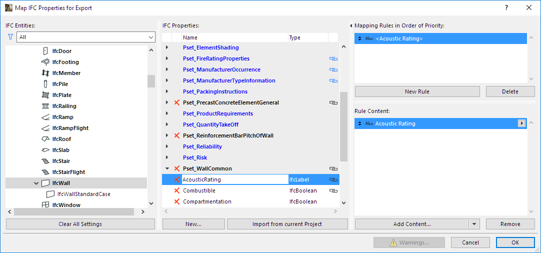
1.Map the user-defined “Acoustic Rating” property (Options > Property Manager) to the “AcousticRating” property defined for the IfcWall.
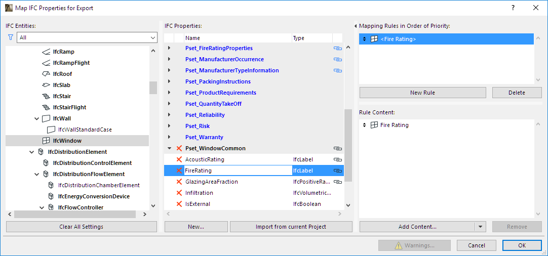
2.Map the “Fire Resistance Rating” parameter of windows to the “FireRating” property defined for the IfcWindow.
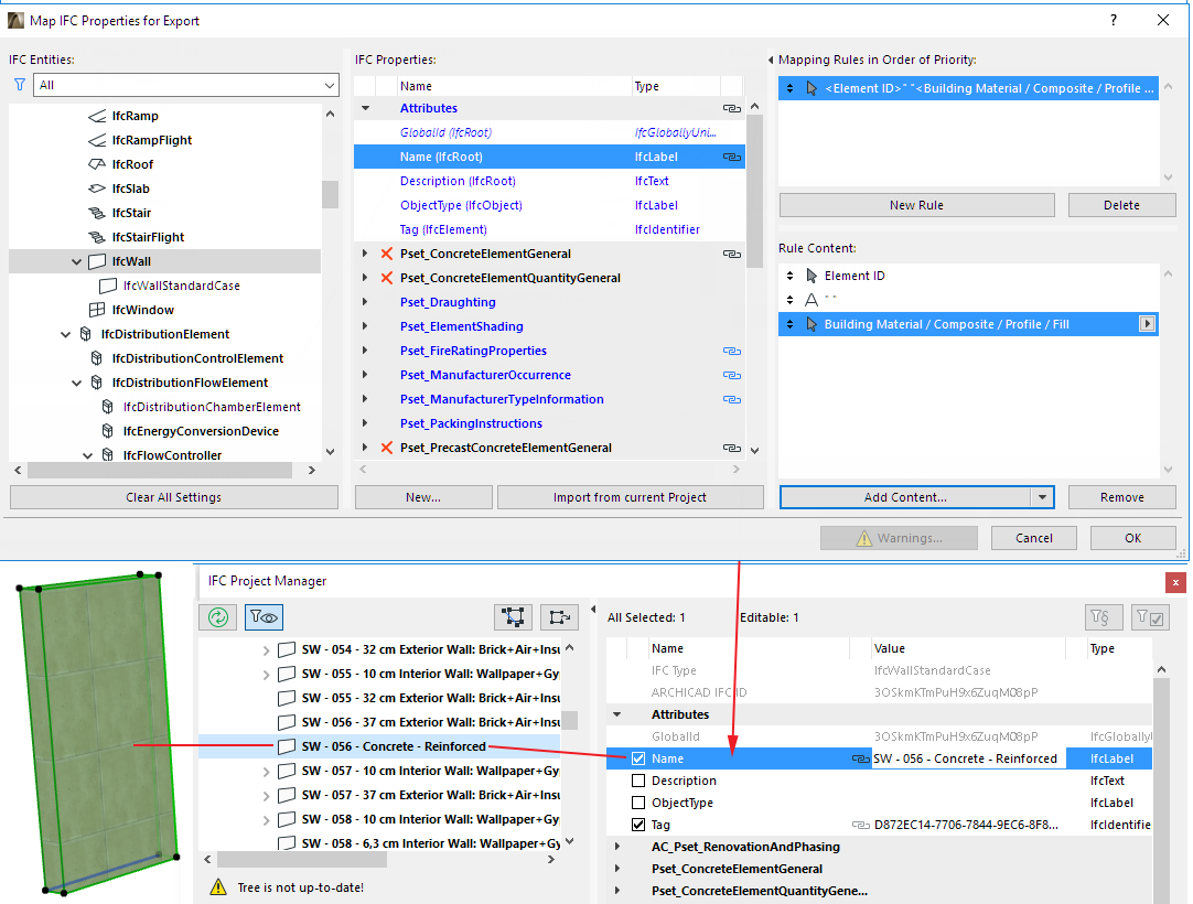
3.Define the “Name” Attribute of IfcWall elements using a combination of Wall “ID” and “Building Material/Composite” Name.
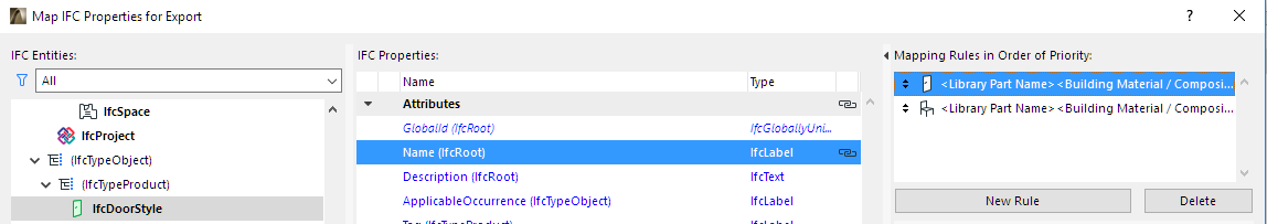
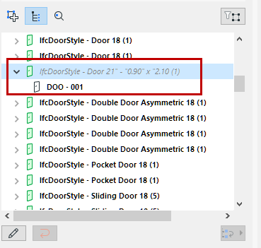
4.Define the “Name” Attribute for IfcDoorStyle by using a fragment of the Door “Library Part name” + static text “-” + “Width” + static text “X” + “Height” (see splitting string-type rule, above).
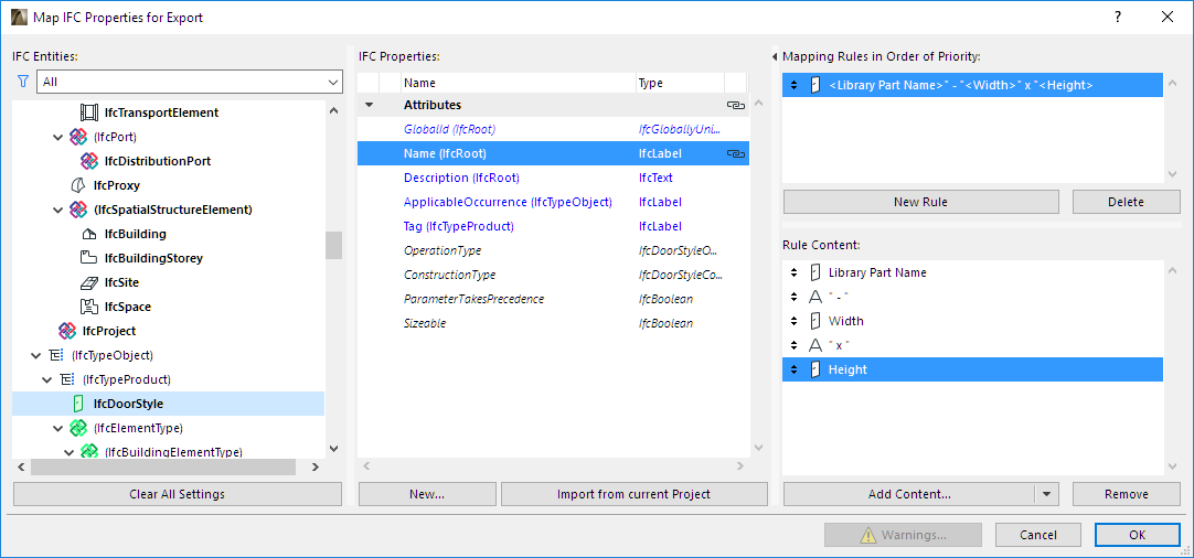
This rule will also overwrite the program’s factory default IfcDoorStyle creation rule (see IFC Type Product) with new IfcDoorStyle names, and will automatically create the corresponding doors (you can double-check the result in the IFC Project Manager).
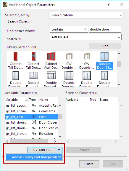
5.Define the “Cost” Property for IfcDoor as Library Part dependent parameter.
For mapping, choose the “gs_list_cost” parameter of the “GS Door” Library Part.
To find this parameter, go to the Add Content drop-down button and choose Library Part parameters. From the appearing dialog box, search for the gs_list_cost parameter as shown:
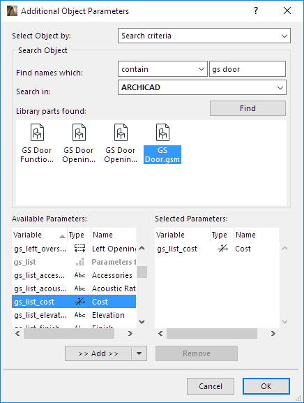

The mapping rule is valid for the Library Parts which are child elements of the “GS Door” subtype (e.g “Door”, “Double Door”, “Metal Door”, etc.).
6.Define the “Cost” Property for IfcDoor as Library Part independent parameter. For mapping, choose the “gs_list_cost” parameter of the “Double Door”.
To find this parameter, go to the Add Content drop-down button and choose Library Part parameters. From the appearing dialog box, first select the Double Door library part, then search for the gs_list_cost parameter as shown. However, make sure to add it as a Libary Part Independent parameter:

7.Define the “Cost” Property for IfcElement as Library Part independent parameter. For mapping, choose the “gs_list_cost” parameter of the “Double Door”. The mapping rule is valid for not just IfcDoor elements but all other Library Parts which will be converted to IFC Entities that are child element of IfcElement (e.g. IfcWindow, IfcFurnishingElement, IfcDistributionElement, IfcTransportElement etc.) and contain the “gs_list_cost” parameter (e.g “Armchair”, “Desk”, “Basin”, “Sink” etc.).
8.You can apply ARCHICAD data mapping rules to the IFC data of IFC Type Product elements. For example, generate the names of Window types (Name Attribute of IfcWindowStyle) from the combination of the Library Part Name, the Width and Height parameters of Window.
Data Conversion for IFC Export
Use this dialog to define which data, in addition to element geometry, should be exported to IFC. Such data can be useful in data exchange with facility management, energy analysis or cost estimation programs.
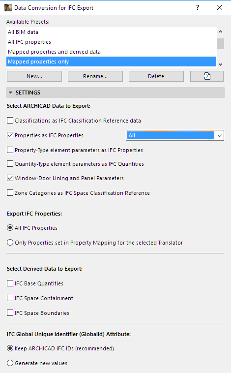
Select ARCHICAD Data to Export
•Classifications as IFC Classification Reference Data
ARCHICAD Classifications are exported as IFC Classification References.
•Properties as IFC Properties
Check to export ARCHICAD Properties exported as IFC Properties. (These properties are defined in Options > Property Manager, and assigned to individual elements in their Settings dialog boxes or through the Interactive Schedule.)
◦Choose to export All properties, or Visible properties only.
Note: The Visible Properties option is only relevant if you have loaded an Add-On which controls property visibility in ARCHICAD. If no such add-on is loaded, then all properties are exported in every case.
•Property-type element parameters as IFC Properties
Check to export ARCHICAD element parameters that convert to IFC Properties (e.g. Library Part and Schedule parameters).
Note: Choosing this option will significantly increase IFC file size. Export parameters only if you know that the target application can read these data.
•Property-type element parameters as IFC Quantities
Check to export parameters that convert to IFC Quantities (e.g. Weight, Length, Area, Volume, Time). Useful for data exchange with programs that can read quantities.
•Zone Categories as IFC Space Classification Reference
Export the Zone Categories data (Code and Name) of ARCHICAD Zones as IFC Classification Reference data (ItemReference and Name).
Export IFC Properties
Choose an option for which IFC Properties and Classification References to export:
•All IFC Properties (all which are visible in the IFC Project Manager, no filter on)
•Only Properties set in the Property Mapping Preset for the selected Translator. (These properties are shown in the IFC Project Manager if you turn on the Show Only Properties from Preview Translator filter)
Select Derived Data to Export
Check one or more types of data to export to the IFC model.
Check this to export Quantity Takeoff parameters (size, area and volume) to IFC. Useful in cost estimation applications.
The following table summarizes the base quantities by entity types automatically calculated and exported when using this option. The values of IfcSite’s base quantities can be set manually at Info > Project Info (Site Gross Perimeter and Site Gross Area).
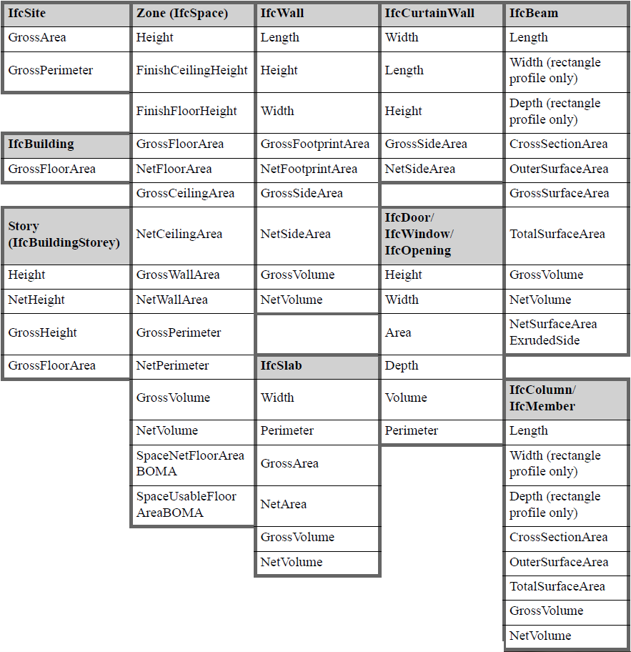
Export IFC Base Quantities
•IFC Space Containment: Export data defining the relationship between ARCHICAD Zones and objects they contain. This feature is useful in facility management applications.
◦Space Containment is relevant only for elements, within an ARCHICAD Zone, which were created using the Object, Lamp, Morph or Slab tools.
-For Object, Lamp or Morph elements: These elements are in space containment only if their home story is the same as that of the Zone, and if the center of the elements’ bounding box falls within the Zone’s 2D polygon.
-A Slab is in space containment if its reference line falls within the Zone top/bottom, and if the Slab polygon falls within the Zone polygon.
◦Click Filter Containment to limit the contents of the Space Containment by their IFC Element Type.
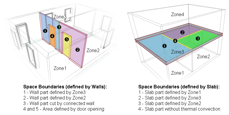
•IFC Space Boundaries: Export geometry data of ARCHICAD Zones. (Useful in thermal calculation applications.)
ARCHICAD Zones include precise geometry data that are useful to thermal calculation software applications. Zones are 3D solids in geometrical aspect and in normal cases are bordered by two slabs and four walls. Space boundaries define the logical connection between ARCHICAD Zones (IfcSpace) and the building elements that enclose them. In practice, Walls, Slabs, Roofs, Windows, Doors etc. all have different thermal conductivity properties. If you activate the “IFC Space boundaries” option, ARCHICAD will export Space boundaries and their relations (IfcRelSpaceBoundary) together with the Zones (IfcSpace) to the IFC file. In other words, ARCHICAD will calculate the position, size and adjacency of the elements that border each Zone. ARCHICAD divides the Zone boundaries according to the areas defined and cut by connected elements and openings.
See also Energy Evaluation: Direct BIM to BEM.
IFC Global Unique Identifier Attribute (GlobalId)
•Keep ARCHICAD IFC ID: IFC GlobalId Attributes of elements (assigned automatically by ARCHICAD) will be retained in the exported IFC model.
◦The “Keep ARCHICAD IFC ID” option is useful when using other programs to compare two IFC model versions arriving from ARCHICAD.
◦This option is recommended when comparing two IFC models in ARCHICAD: see Detect IFC Model Changes.
◦This option is recommended for the BCF workflow, in which the roundtrip data exchange identifies model elements using their GlobalId Attributes: see Export/Import Markup Using BIM Collaboration Format (BCF).
•Generate new values: Each new exported IFC file will generate brand new GlobalIds for the elements, so that each new exported version is entirely separate from the previous versions.
Note: This option has no effect on the Merge to IFC Model export process.
See also How to Control Global ID (IFC Attribute) Based on ARCHICAD Project Info.
Unit Conversion for IFC Export
Set unit types globally for the export of all coordinates, geometric parameters and “Measure”-type IFC Properties.