
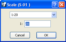
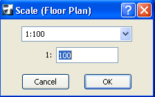
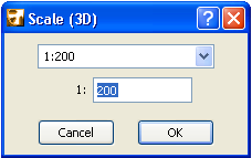
To set the scale of the currently active window, choose the Document > Floor Plan Scale command. (The name of the command varies depending on which window is active.)
You can have a separate scale in effect for each window.
Select either a standard scale from the pop-up list or type a nonstandard scale into the input field. The name of the given window is displayed in the caption of the dialog box.
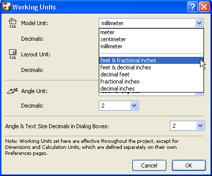
Standard scales are shown according to either metric or US standards, depending on the Length Unit setting made in the Working Units dialog box.
See Working Units.
You can also use the Scale pop-up from the Quick Options Palette to reset the scale of the current window.
After setting a scale, what you see is a preview of the Project if it were printed or plotted at that scale. To make a zoomed view match the view at the currently set scale, choose View > Zoom > Actual Size (or click the zoom button) after setting the scale.
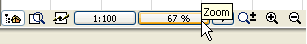
Actual Size is the equivalent of the 100% scale value.
The 2D Symbol of some GDL Objects (see the parameter) can be set to be sensitive to the current scale: the symbol varies depending on the current scale.
See 2D Detail Level.
Model Size vs. Paper Size Elements
Model Size elements are rescaled along with the model whenever you change the project scale. Model size elements include all construction elements such as walls, objects, slabs etc.
Paper Size elements are printed or displayed on the screen at the size you specify, regardless of the scale selected for the Project. For elements that do not have any real size, such as dimensions and arrowheads, you can specify a fixed size defined in either points or millimeters.
Either Model Size or Paper Size: The following elements may be either model size (scaled with the plan) or paper size (scale independent):
•Text Blocks created with the Text tool: Choose Model or Paper size.
See Text Tool Settings.
•Dashed and symbol line types: Choose Model or Paper size.
•Vectorial, symbol and image fill types: Choose Model or Paper size.
Set a Different Scale for Each View
As you save views of your project, the scale is saved along with the view. Naturally, you will vary the scale as your project develops and you save multiple views at different scales for different purposes, using the Scale option.
See View Settings.
Set a Separate Printing Scale for 2D Document
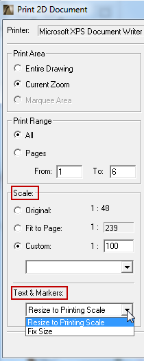
The Scale options in the Print 2D Document and Plot 2D Document dialog boxes allow you to specify a Custom printing scale each time you print or plot your work from a Floor Plan or other 2D window.
See Print 2D Document and Plot 2D Document.
The Text and Markers options enable you to reduce/enlarge text and markers as the printing scale is changed, or keep them at a fixed (paper) size.
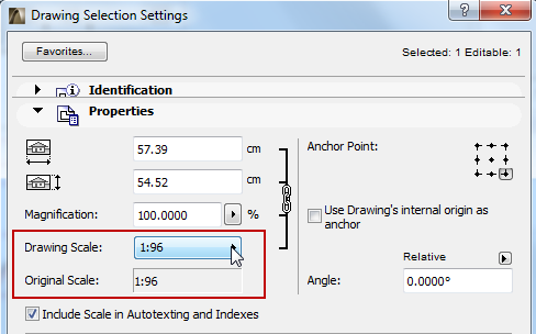
Drawing Scale
Drawings based on an ArchiCAD view have a Drawing Scale. By default, this Drawing Scale is the same as the Original Scale (the scale of the Drawing’s source view), but you can customize the Drawing Scale in Drawing Settings.
See Drawing Settings.
Customizing the Drawing scale has no effect on the scale of objects within the drawing; it is equivalent to a graphical resizing of the Drawing, like the effect of magnifying a document with a copy machine.